Revolutionize Your Smart Home with Precision Temperature Control!


Digital Temperature Sensor
The EzloPi smart devices provide automation through simple, customizable use with our open-source EzloPi platform, making daily life easier and improving human-machine interactions.
Before moving into this example, it is very important to know about the device registration, provisioning and converting the ESP32 device into an EzloPi device along with knowledge of Web Flasher, MiOS Mobile Application for Android/iOS and the MiOS Web Application.
1. About this example
This example aims to create a seamless and intelligent integration between the KY-001 Digital Temperature Sensor Module and the EzloPi device.
With the user-friendly MiOS mobile and web application, users can remotely access and monitor the temperature information and make informed decisions to optimize energy consumption and enhance comfort. This also allows for intelligent automation, allowing users to set custom triggers and actions based on temperature thresholds values, enhancing energy efficiency and comfortable living.
2. Circuit Setup & Interfacing
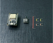
The following components are required for interfacing the digital temperature sensor module with the EzloPi device:
- ESP32 as EzloPi smart device.
- KY-001 Module with DS18B20 Digital Temperature Sensor.
The wiring diagram of ESP32 32 pin is represented as follows:


The following connections are made in order to complete the entire circuit setup.
From ESP32 (32 pins) to the KY-001 Module:
- Connect the GND from the ESP32 to the negative (-ve) pin as GND of the module.
- Connect the 3v3 pin from the ESP32 to the middle pin for voltage supply.
- Connect the D21 pin from the ESP32 to the signal (S) pin of the module.
The wiring diagram of ESP32 38 pin is also represented as below:

The following connections are made in order to complete the entire circuit setup.
From ESP32 (38 pins) to the KY-001 Module:
- Connect the GND from the ESP32 to the negative (-ve) pin as GND of the module.
- Connect the 3v3 pin from the ESP32 to the middle pin for voltage supply.
- Connect the IO21 pin from the ESP32 to the signal (S) pin of the module.
3. Interfacing theKY-001 Temperature Sensor Module using EzloPi Web Flasher
1. Set up your device/hardware by visiting config.ezlopi.com
- Log in using the credentials which you just set earlier while signing up.

- Now click on Connect Device and a pop-up window will appear

Now, select COM Port to which your ESP32 device is connected. In our case, the COM3 port is used.
Click Connect.

- If you are new to this and it’s your first time configuring, select Create new Device ID. Enter Wifi SSID and Wifi Password.
- In the Device Configuration, tab click on One Wire.

- A Digital Input window will open for inputting the following parameters:
- Set a device name of your choosing. In our case, we will set it to Temperature.
- Set Out GPIO to 21.
- Now Click the Apply button. After clicking the apply button you can see a table of your setting in the Current configuration tab.
- Press the Flash Device button.

- A window will appear on the bottom left side of the screen displaying “Please press BOOT button while flashing begins.”
- Hold the BOOT button down until the next window appears on the bottom left side of the screen which says “Installation prepared. Please release the boot button now.”

- Release the BOOT button from your ESP32 when this pop-up on the bottom right window appears.

- After some time, a popup will appear saying Device Flashed Successfully! This means that your device has been set up successfully.
4. MiOS App
You can download the MIOS Android app from the Google Play Store and Apple App Store.


- After downloading the app, proceed to install the application and open it.

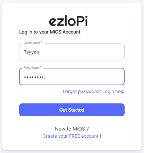
- Using the MIOS mobile application, create a new Ezlo Cloud account using the sign-up option. If you already have an account, you may proceed to log in.

- After successfully logging in, you will be able to see the number of controllers connected such as a lamp, fan, or any other device in the MiOS app. Tap on any controller of your desired ID:


- After opening the dashboard, you will be able to see the tile of your connected device.
- As we can see above in the MiOS mobile app dashboard, the temperature sensor module tile is showing the current temperature value.
5. MiOS Web Application
- After configuring the controller with the EzloPi web flasher, head to ezlogic.mios.com
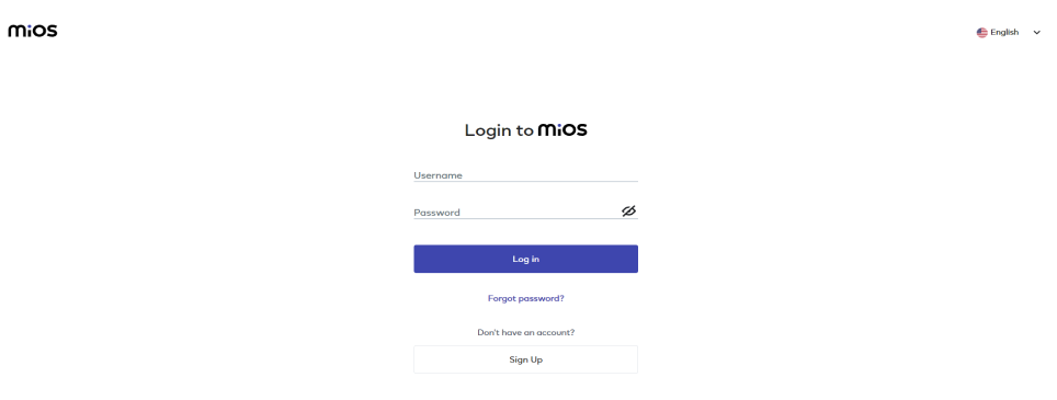
- Use the same credentials to log in that you used for configuring the controller with the web flasher.

- As seen in the web dashboard, the KY-001 module connected to the EzloPi device is displaying the ambient temperature readings.

eZlopie Products A single-channel 5V relay module $00.00

eZlopie Products Momentary switch $00.00

eZlopie Products Level Shifter Module (BSS138) $00.00

eZlopie Products ESP32
$00.00

eZlopie Products AC Lamp and Holder
$00.00

