


The EzloPi smart devices provide automation through simple, customizable use with our open-source EzloPi platform, making daily life easier and improving human-machine interactions.
Before moving into this example, it is very important to know about the device registration, provisioning and converting the ESP32 device into an EzloPi device along with knowledge of Web Flasher, MiOS Mobile Application for Android/iOS and the MiOS Web Application.
1. About this example
The smart mood lighting system uses the LTR303ALS luminosity sensor and a flexible neon LED strip integrated with the EzloPi device. The LTR303ALS sensor continuously monitors ambient light levels, adjusting the brightness and color of the neon LED strip to create optimal lighting based on the surrounding environment. The system offers customizable lighting options such as brightness control, providing an energy-efficient and personalized mood lighting experience. Ideal for home automation setups, this project allows users to enhance their living spaces with adaptive and intelligent lighting solutions using the EzloPi smart platform.
3. Circuit Diagram & Interface
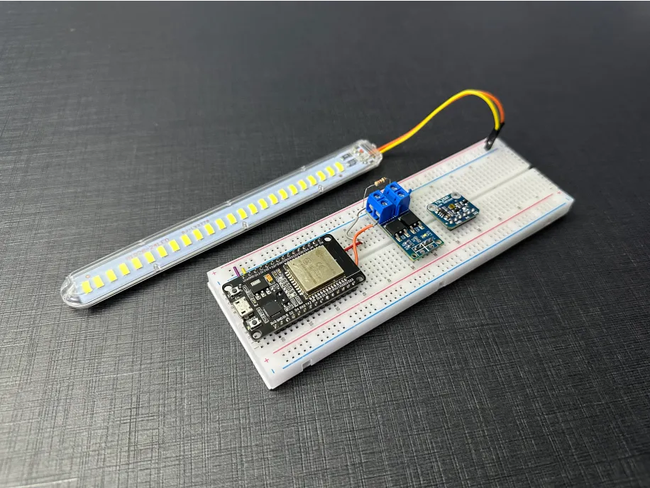
The following components are required for interfacing with the EzloPi device:
- ESP32 as an EzloPi smart device.
- LTR303ALS Luminosity sensor.
- XY-MOS, high-power dual MOSFET driver module.
- Flexible neon LED strip.
- 12V Power supply.
The wiring diagram for the ESP32 30 pin is represented as below:
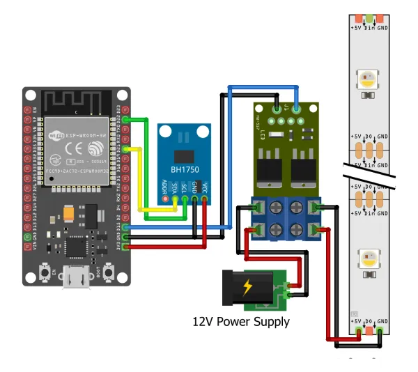
The following connections are made in order to complete the circuit setup:
From ESP32 to the LTR303ALS Luminosity sensor:
| ESP32 | LTR303ALS |
| 3V3 | VCC |
| GND | GND |
| D21 | SDA |
| D22 | SCL |
From ESP32 to the MOSFET driver module:
| ESP32 | MOSFET driver module |
| D15 | Trig |
| GND | GND |
From Power Supply to the MOSFET driver module:
| Power Supply | MOSFET driver module |
| VCC | SUPPLY+ |
| GND | SUPPLY- |
From MOSFET driver module to LED Strip:
| MOSFET Driver | LED Strip |
| LOAD+ | 5V |
| LOAD- | GND |
4. Interfacing the Light/Luminosity Sensor (LTR303ALS) & LED Strip using the EzloPi Web Flasher
1. Set up your device/hardware by visiting config.ezlopi.com

- Log in using the credentials which you just set earlier while signing up.
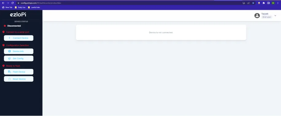
- Now, click on the Connect Device button and a pop-up window will appear.
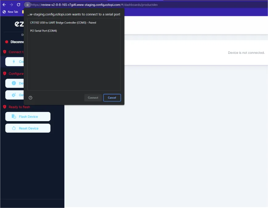
- Now, select COM Port to which your ESP32 device is connected. In our case, the COM3 port is used.
Click Connect
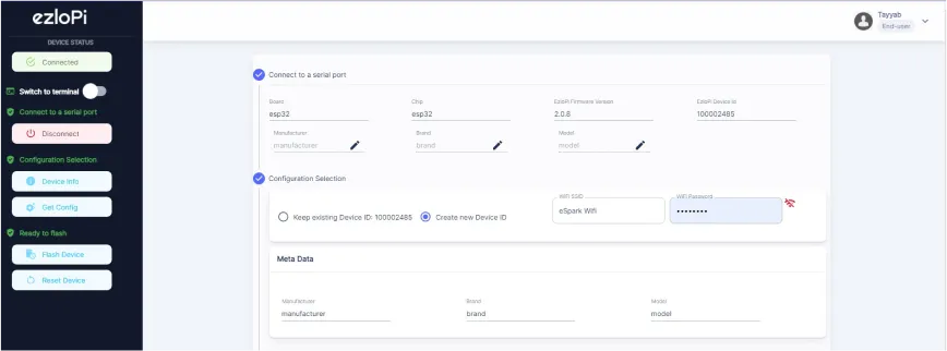
- If you are new to this and it's your first time configuring, select Create new Device ID. Enter Wifi SSID and Wifi Password.
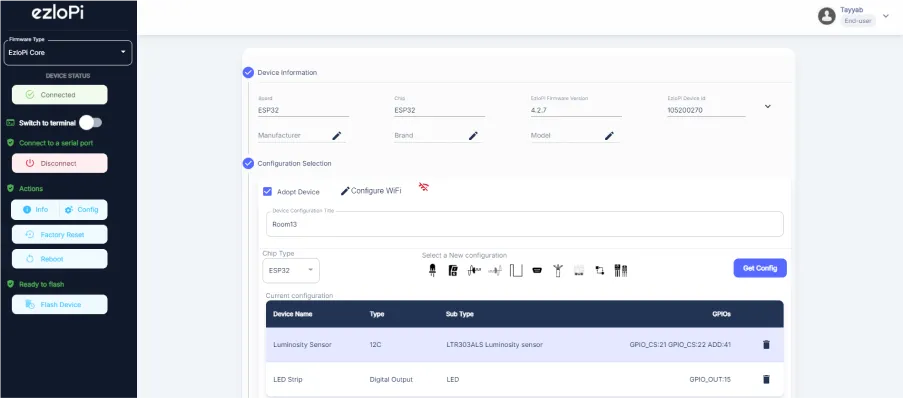
- In the Device Configuration, tab click on I2C.
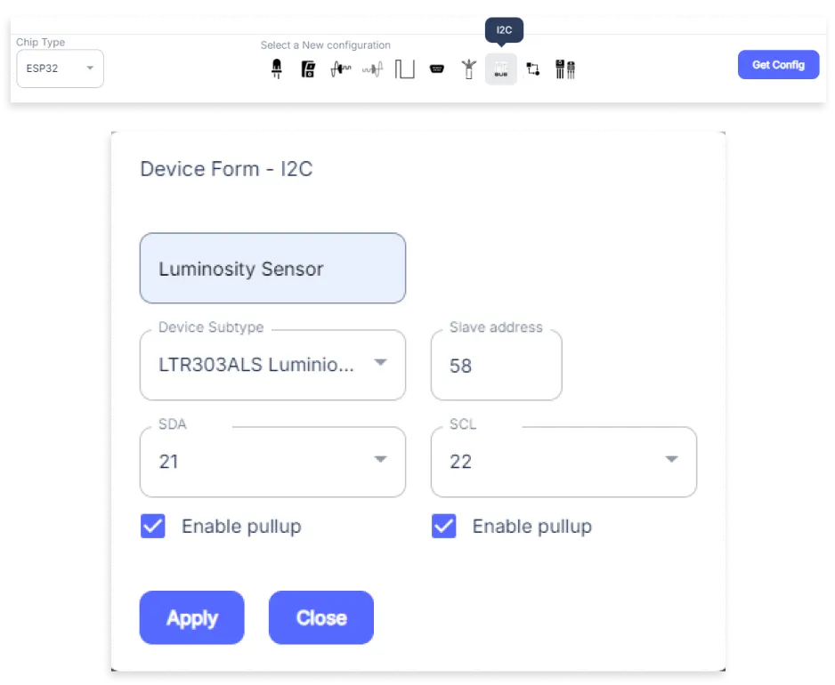
- An I2C window will be opened for inputting the following parameters:
- Set a Device name of your choosing. In our case, we set it to Luminosity Sensor.
- Set Device subtype to LTR303ALS Luminosity Sensor.
- Set Slave address to 41.
- Set SDA pin to GPIO21.
- Set SCL pin to GPIO22.
- Check both Enable pullup boxes.
- Then Click Apply Button.
- Again, In the Device Configuration, tab click on PWM.
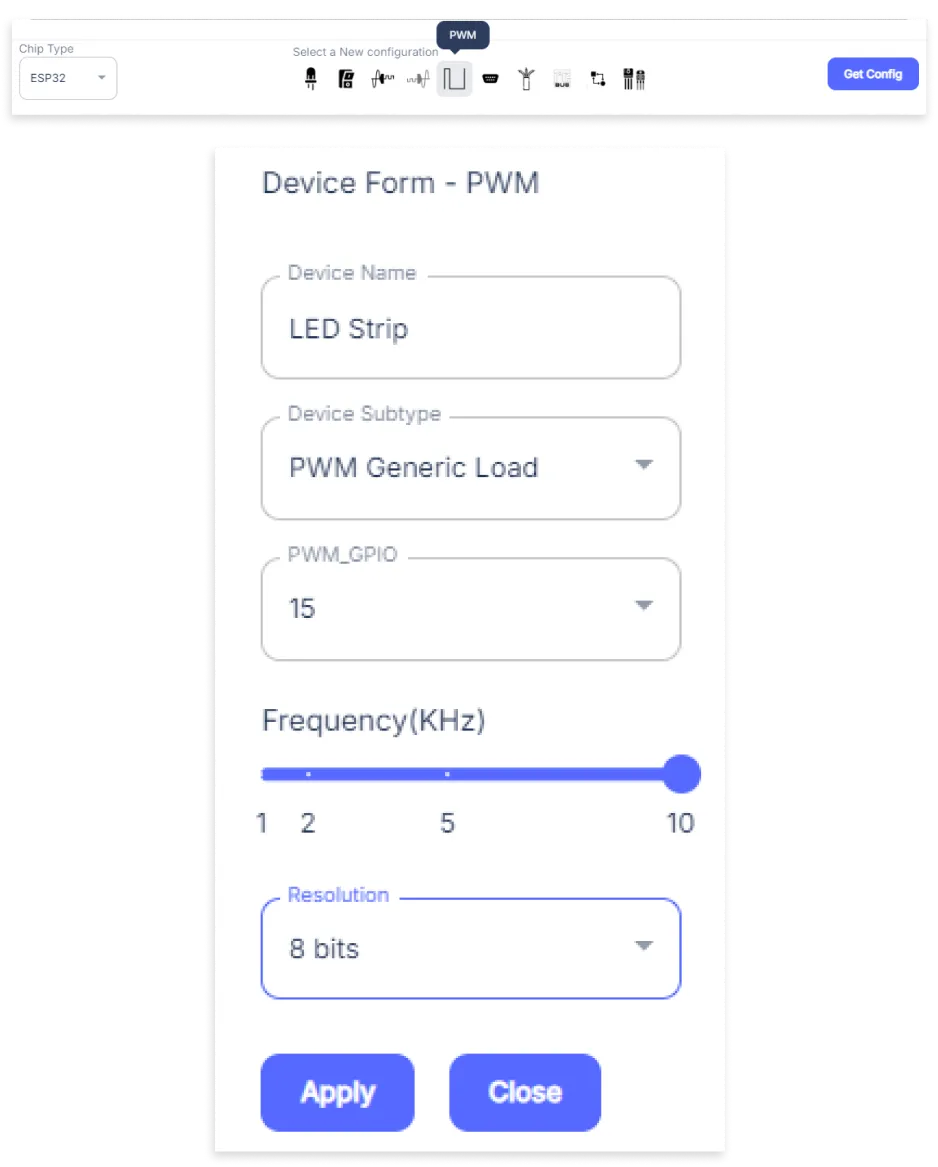
- A PWM window will be opened for inputting the following parameters:
- Set a Device name of your choosing. In our case, we set it to LED Strip.
- Set Device subtype to PWM Generic Load.
- Set the PWM_GPIO pin to 15.
- Set the Frequency from its Slider.
- Set the Resolution to 8-bit.
- Then Click Apply Button
- After clicking the apply button you can see a table of your setting in the device configuration tab.
- Press the Flash Device button.
- A window will appear on the bottom right side of the screen displaying “Please press BOOT button while flashing begins.”
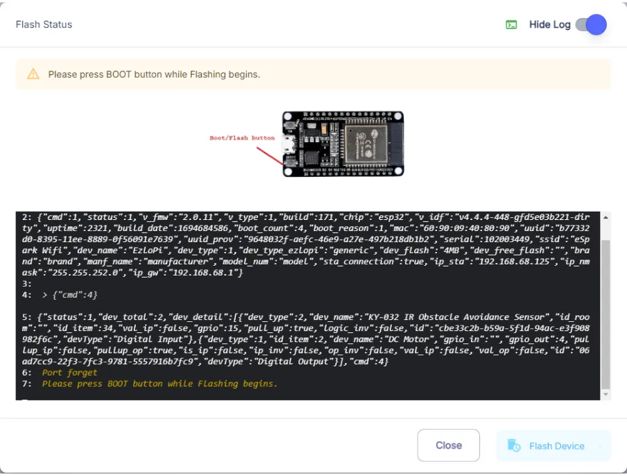
- Hold the BOOT button down until the next window appears on the bottom right side of the screen which says “Installation prepared. Please release the boot button now.”
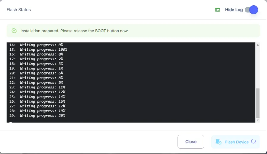
- Release the BOOT button from your ESP32 when this pop-up on the bottom right window appears.
- After some time, a popup will appear saying Device Flashed Successfully! This means that your device has been set up successfully.
5. MiOS App
You can download the MIOS Android app from the Google Play Store and Apple App Store.


- After downloading the app, proceed to install the application and open it.

- Using the MIOS mobile application, create a new Ezlo Cloud account using the sign-up option. If you already have an account, you may proceed to log in.

- After successfully logging in, you will be able to see the number of controllers connected such as a lamp, fan, or any other device in the MiOS app. Tap on any controller of your desired ID:
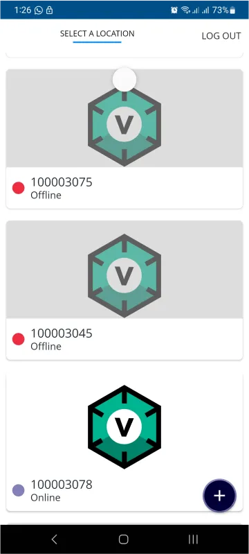
- You will be able to see the status of your controller whether it is online or offline. Access the device dashboard, and tap the device. The following view of the dashboard will appear:
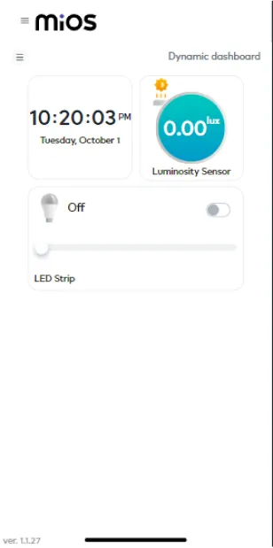
- Here, as seen in the MiOS mobile app above, we can see the LED strip and luminosity sensor tiles. The above picture shows that when the LED strip is OFF then the luminosity sensor also shows no or zero intensity.
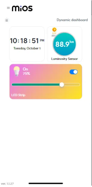
- Here, it can be seen that when the LED strip is turned ON and with certain intensity then the luminosity sensor also detects the light of the LED Strip and also shows its intensity.
6. MiOS Web Dashboard
- After configuring the controller with the EzloPi web flasher, head to ezlogic.mios.com

- Use the same credentials to log in that you used for configuring the controller with the web flasher.
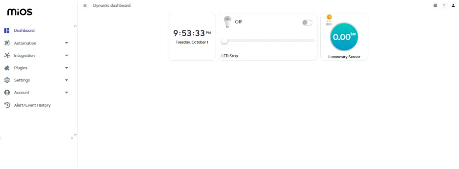
- As seen in the MiOS web app, we can see the LED strip and luminosity sensor tiles. The above picture shows that when the LED strip is OFF then the luminosity sensor also shows no or zero intensity.
MeshBots:
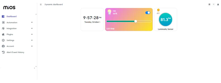
- Here, it can be seen that when the LED strip is turned ON and with certain intensity then the luminosity sensor also detects the light of the LED Strip and also shows its intensity.


