


The EzloPi smart devices provide automation through simple, customizable use with our open-source EzloPi platform, making daily life easier and improving human-machine interactions.
Before moving into this example, it is very important to know about the device registration, provisioning and converting the ESP32 device into an EzloPi device along with knowledge of Web Flasher, MiOS Mobile Application for Android/iOS and the MiOS Web Application.
1. About this example
The smart security system project integrates the FC-51 proximity sensor and KY-025 reed switch module with the EzloPi device to enhance home or office security. The FC-51 sensor detects any approaching objects or intrusions within a set range, while the KY-025 reed switch monitors the status of doors or windows. If any unexpected movement or entry is detected, the system can trigger alerts or activate additional security measures, such as alarms or notifications. This system provides real-time monitoring, ensuring prompt responses to potential security breaches. The EzloPi device manages sensor inputs and processes security actions efficiently to enhance the user experience.
3. Circuit Diagram & Interface
The following components are required for interfacing with the EzloPi device:
- ESP32 as an EzloPi smart device
- FC-51 Proximity sensor
- KY-025 Reed switch module
The wiring diagram for the ESP32 30 pin is represented as below:
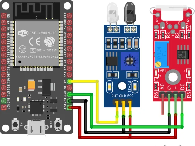
The following connections are made in order to complete the circuit setup:
From ESP32 to the FC-51 Proximity sensor:
| ESP32 | FC-51 Proximity sensor |
| 3V3 | VCC |
| GND | GND |
| D4 | OUTL |
From ESP32 to KY-025 Reed switch module:
| ESP32 | KY-025 |
| 3V3 | +(VCC) |
| GND | G(GND) |
| D15 | D0 |
4. Interfacing the Proximity Sensor & Reed Switch using the EzloPi Web Flasher
1. Set up your device/hardware by visiting config.ezlopi.com

- Log in using the credentials which you just set earlier while signing up.
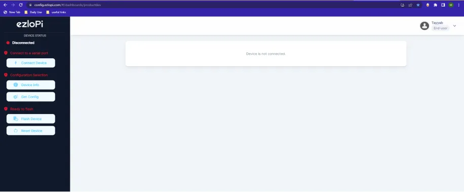
- Now, click on the Connect Device button and a pop-up window will appear.
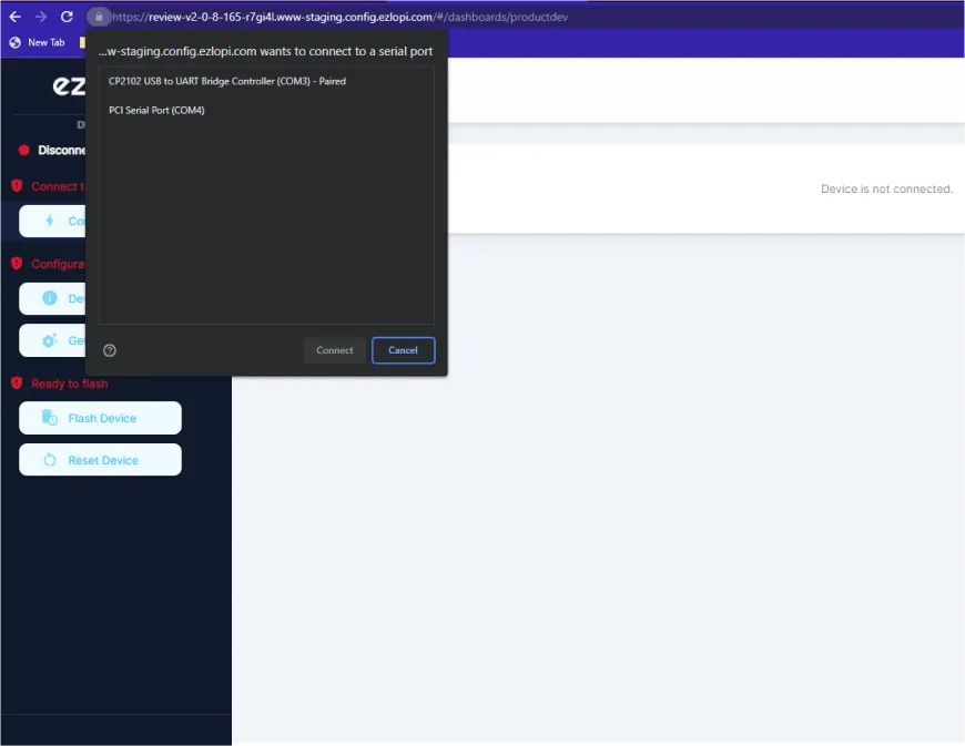
- Now, select COM Port to which your ESP32 device is connected. In our case, the COM3 port is used.
Click Connect
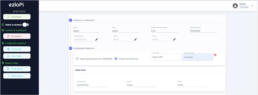
- If you are new to this and it's your first time configuring, select Create new Device ID. Click on the Configure Wifi button. Enter Wifi SSID and Wifi Password.
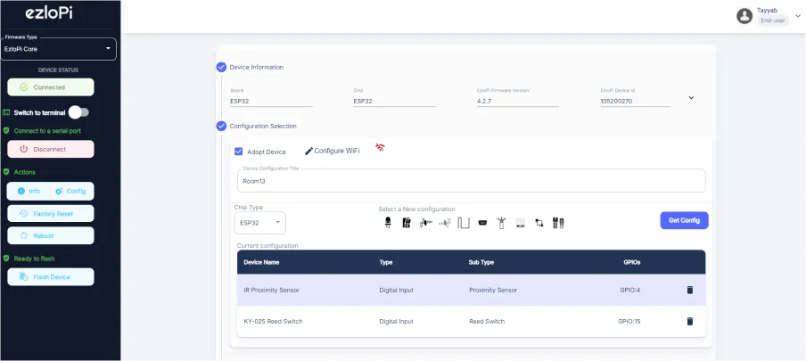
- In the Device Configuration, tab click on Digital Input.
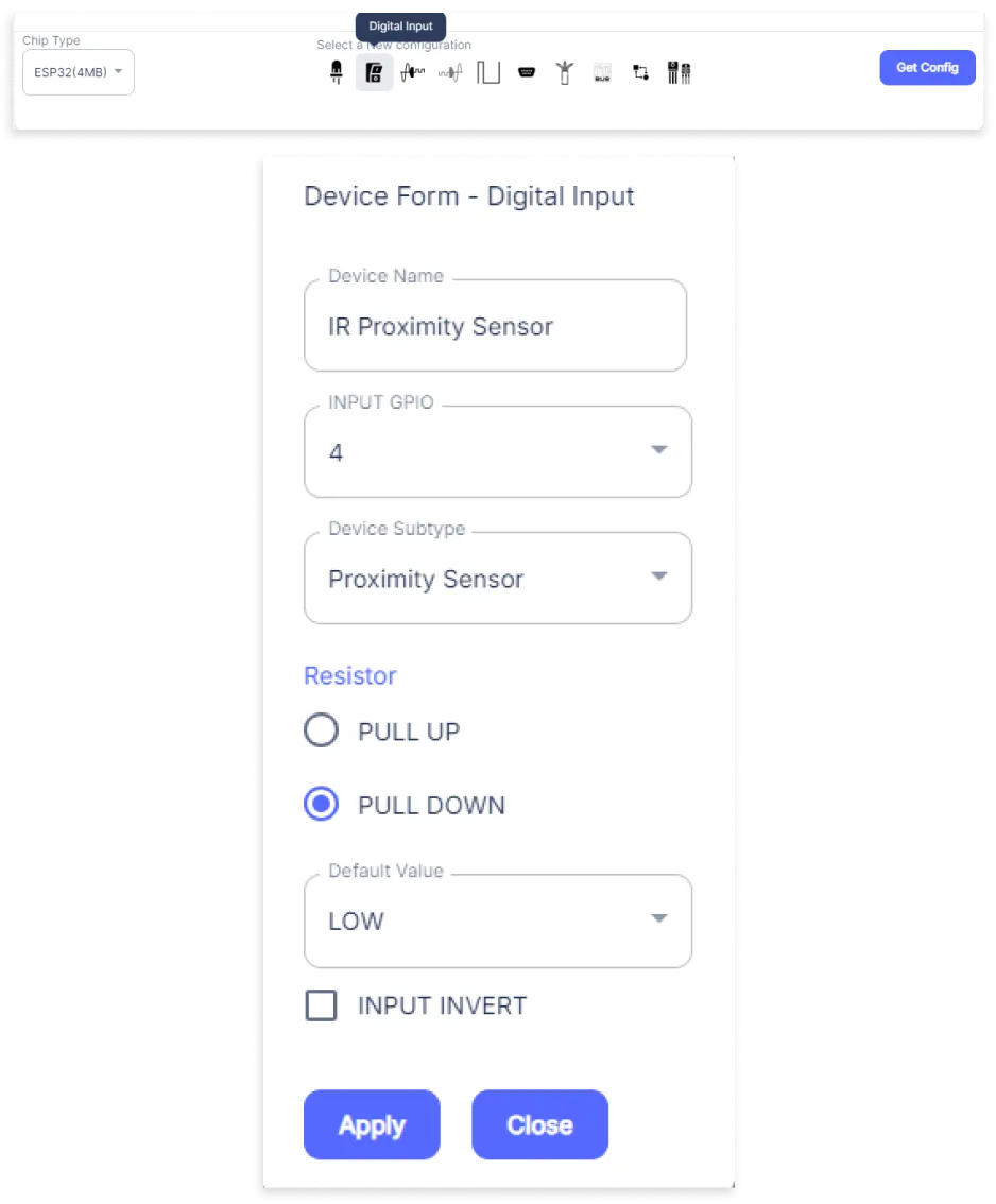
- A Digital Input window will open for inputting the following parameters:
- Set a Device name of your choosing. In our case, we set it to IR Proximity Sensor.
- Set OUT GPIO to 4.
- Set Device Subtype to IR Proximity Sensor.
- Set the Resistor to PULL DOWN.
- Set Default value to LOW.
- Then Click Apply Button.
- Again, In the Device Configuration, tab click on Digital Input.
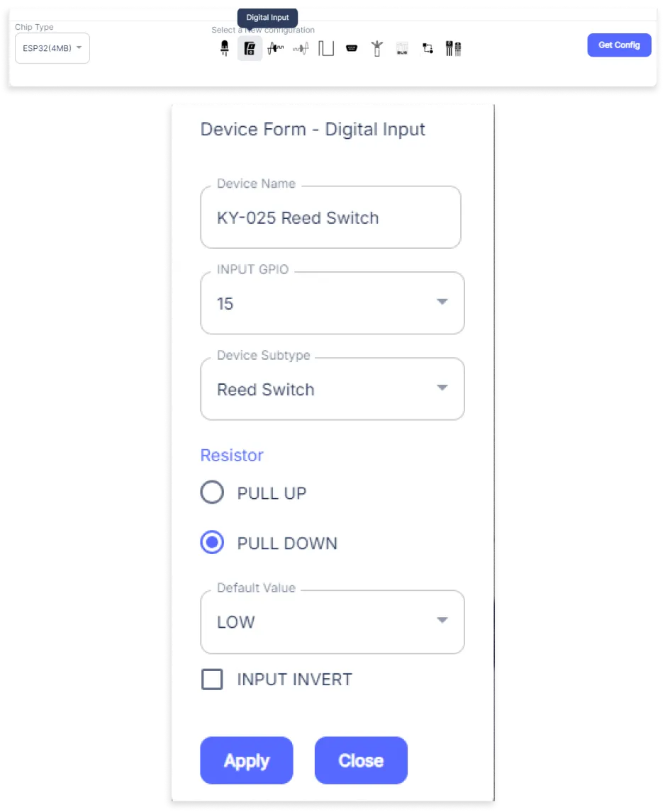
- A Digital Input window will open for inputting the following parameters:
- Set a Device name of your choosing. In our case, we set it to KY-025 Reed Switch.
- Set OUT GPIO to 15.
- Set Device Subtype to Reed Switch.
- Set the Resistor to PULL DOWN.
- Set Default value to LOW.
- Then Click Apply Button
- After clicking the apply button you can see a table of your setting in the device configuration tab.
- Press the Flash Device button.
- A window will appear on the bottom right side of the screen displaying “Please press BOOT button while flashing begins.”
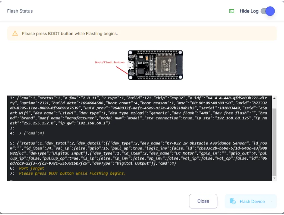
- Hold the BOOT button down until the next window appears on the bottom right side of the screen which says “Installation prepared. Please release the boot button now.”
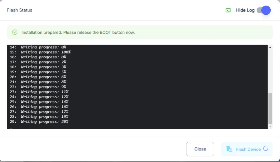
- Release the BOOT button from your ESP32 when this pop-up on the bottom right window appears.
- After some time, a popup will appear saying Device Flashed Successfully! This means that your device has been set up successfully.
5. MiOS App
You can download the MIOS Android app from the Google Play Store and Apple App Store.


- After downloading the app, proceed to install the application and open it.

- Using the MIOS mobile application, create a new Ezlo Cloud account using the sign-up option. If you already have an account, you may proceed to log in.

- After successfully logging in, you will be able to see the number of controllers connected such as a lamp, fan, or any other device in the MiOS app. Tap on any controller of your desired ID:
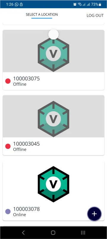
- You will be able to see the status of your controller whether it is online or offline. Access the device dashboard, and tap the device. The following view of the dashboard will appear:
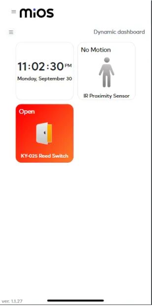
- Here, as seen in the MiOS mobile app above, we can see the IR proximity sensor and reed switch tiles. The above figure indicates when no motion is detected by proximity sensor it shows ‘No Motion’ message while the reed switch shows an ‘Open’ message which means no person or object is detected by it also.
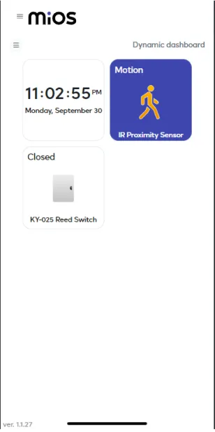
- Now, it can be seen that when some motion is detected by IR proximity sensor, the tile message now changes to ‘Motion’ whereas the reed switch also detects something that's why it now shows a ‘Closed’ message.
6. MiOS Web Dashboard
- After configuring the controller with the EzloPi web flasher, head to ezlogic.mios.com

- Use the same credentials to log in that you used for configuring the controller with the web flasher.
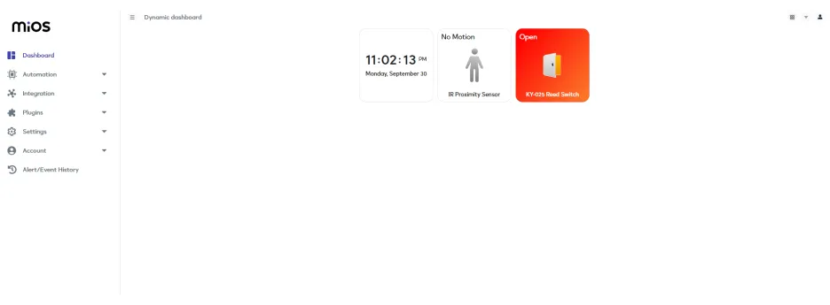
- Here, as seen in the MiOS web app above, we can see the IR proximity sensor and reed switch tiles. The above figure indicates when no motion is detected by proximity sensor it shows ‘No Motion’ message while the reed switch shows an ‘Open’ message which means no person or object is detected by it also.
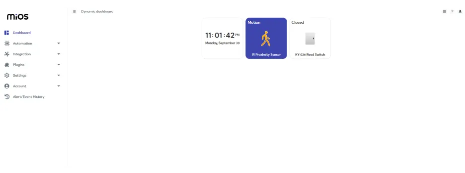
- Now, it can be seen that when some motion is detected by IR proximity sensor, the tile message now changes to ‘Motion’ whereas the reed switch also detects something that's why it now shows a ‘Closed’ message.


