


The EzloPi smart devices provide automation through simple, customizable use with our open-source EzloPi platform, making daily life easier and improving human-machine interactions.
Before moving into this example, it is very important to know about the device registration, provisioning and converting the ESP32 device into an EzloPi device along with knowledge of Web Flasher, MiOS Mobile Application for Android/iOS and the MiOS Web Application.
1. About this example
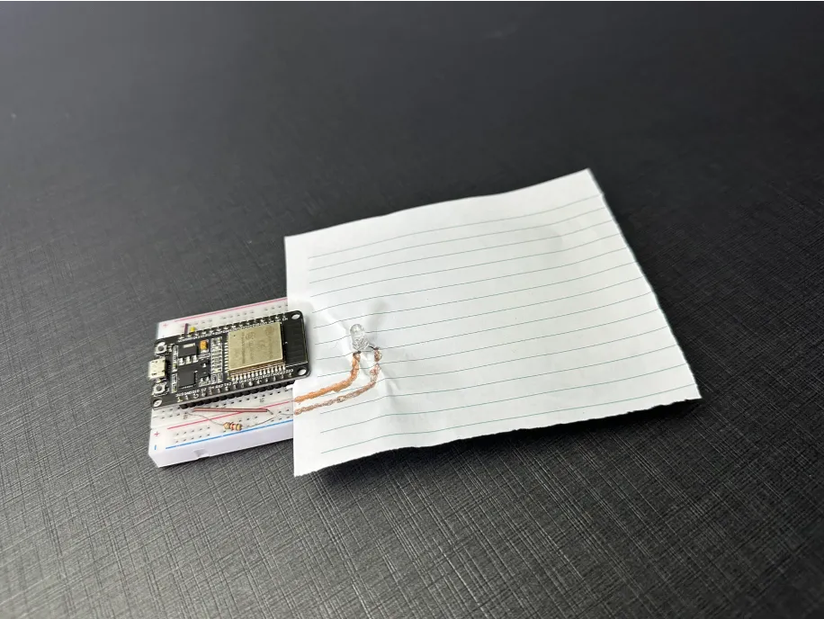
In this project, a conductive pen is used to draw electrical connections for the LED interfaced with the EzloPi device. By using the conductive ink from the pen, the need for traditional wiring or soldering is eliminated, making the design more flexible and customizable. This approach allows for quick prototyping and easy modifications in the circuit layout. The EzloPi device manages the LED's behavior, interaction using the MiOS user interface, enabling status monitoring of the LED. This project demonstrates an innovative way of creating simple electronic circuits using conductive ink technology.
3. Circuit Diagram & Interface
The following components are required for interfacing with the EzloPi device:
- ESP32 as an EzloPi smart device.
- Conductive pen
- LED with a current limiting resistor of 82 Ohms value.
The wiring diagram for the ESP32 30 pin is represented as below:
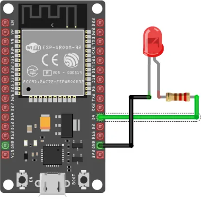
The following connections are made in order to complete the circuit setup:
From ESP32(30 pins) to the LED:
| ESP32 | LED | Resistor |
| D4 | - | Terminal no. 1 |
| GND | Cathode | - |
| - | Anode | Terminal no. 2 |
4. Interfacing the LED using the EzloPi Web Flasher
1. Set up your device/hardware by visiting config.ezlopi.com

- Log in using the credentials which you just set earlier while signing up.
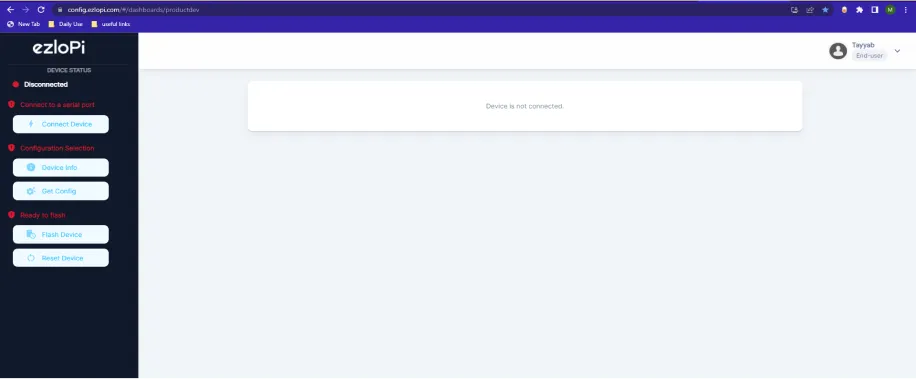
- Now, click on the Connect Device button and a pop-up window will appear.
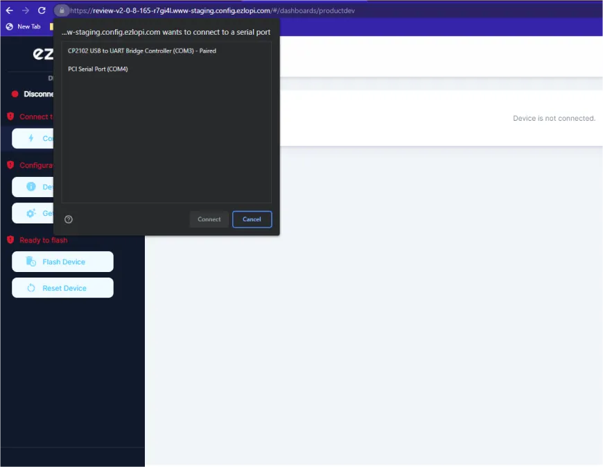
- Now, select COM Port to which your ESP32 device is connected. In our case, the COM3 port is used.
Click Connect
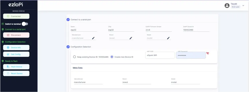
- If you are new to this and it's your first time configuring, select Create new Device ID. Click on the Configure Wifi button. Enter Wifi SSID and Wifi Password.
- In the Device Configuration, tab click on Digital Output.
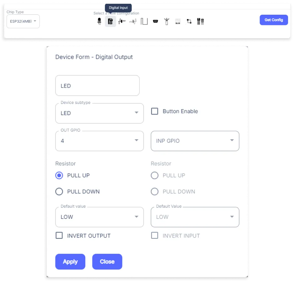
- A Digital Output window will open for inputting the following parameters:
- Set a device name of your choosing. In our case, we set it to LED.
- Set Device subtype to LED.
- Set OUT GPIO to 4.
- Set Resistor to PULL UP.
- Set the default value to LOW.
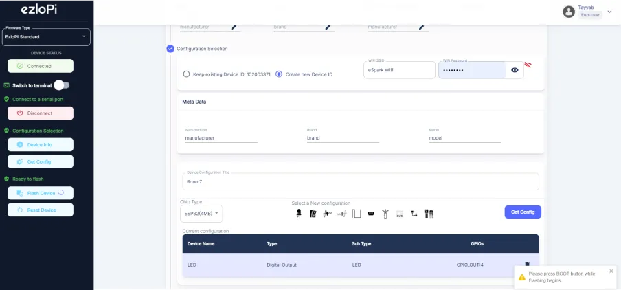
- Then Click Apply Button.
- A window will appear on the bottom right side of the screen displaying “Please press BOOT button while flashing begins.”
- Hold the BOOT button down until the next window appears on the bottom right side of the screen which says “Installation prepared. Please release the boot button now.”
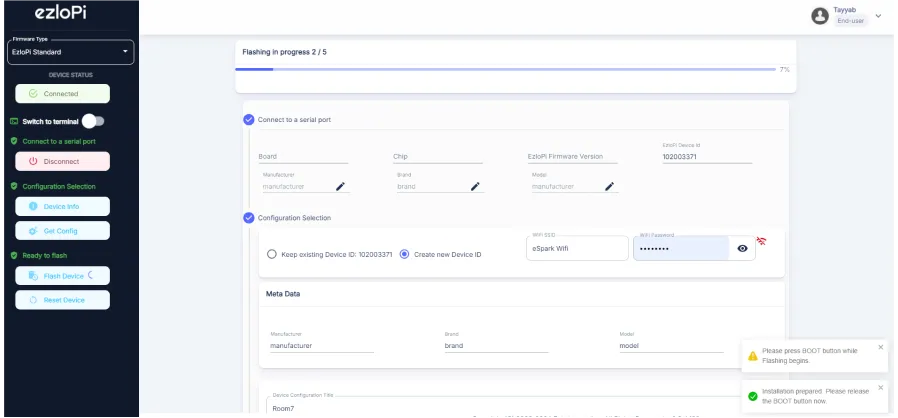
- Release the BOOT button from your ESP32 when this pop-up on the bottom right window appears.
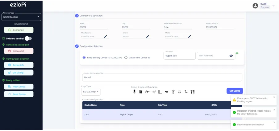
- After some time, a popup will appear saying Device Flashed Successfully! This means that your device has been set up successfully.
5. MiOS App
You can download the MIOS Android app from the Google Play Store and Apple App Store.


- After downloading the app, proceed to install the application and open it.

- Using the MIOS mobile application, create a new Ezlo Cloud account using the sign-up option. If you already have an account, you may proceed to log in.

- After successfully logging in, you will be able to see the number of controllers connected such as a lamp, fan, or any other device in the MiOS app. Tap on any controller of your desired ID:
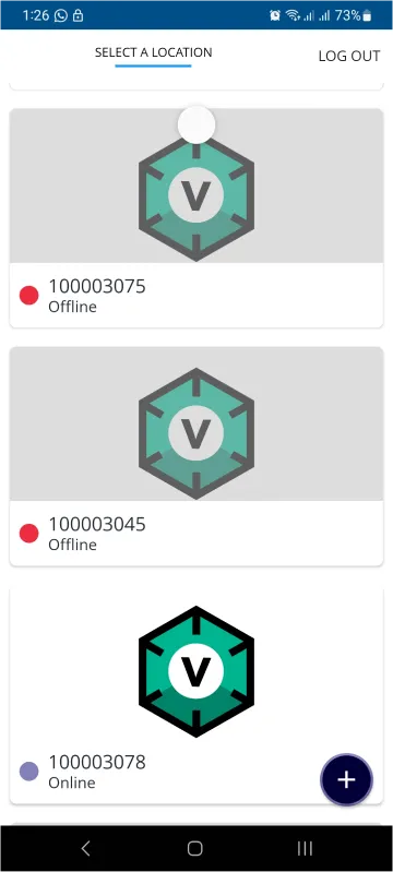
- You will be able to see the status of your controller whether it is online or offline. Access the device dashboard, and tap the device. The following view of the dashboard will appear:
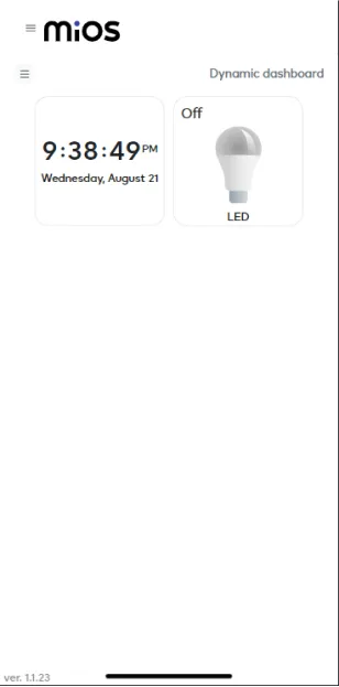
- After opening the MiOS mobile dashboard, you will be able to see the tile of your connected device. The LED will turn ‘ON’ when we draw the wires from the conductive pen from EPS32 to the LED and resistor.
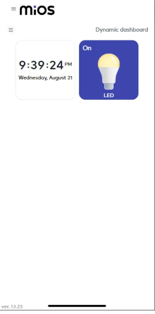
- Now, we can see that the conductive pen works as a wire, the state of the LED is controlled by drawing wires by the conductive pen.
6. MiOS Web Dashboard
- After configuring the controller with the EzloPi web flasher, head to ezlogic.mios.com

- Use the same credentials to log in that you used for configuring the controller with the web flasher.
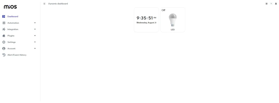
- After opening the MiOS web dashboard, you will be able to see the tile of your connected device. The LED will turn ‘ON’ when we draw the wires from the conductive pen from EPS32 to the LED and resistor.
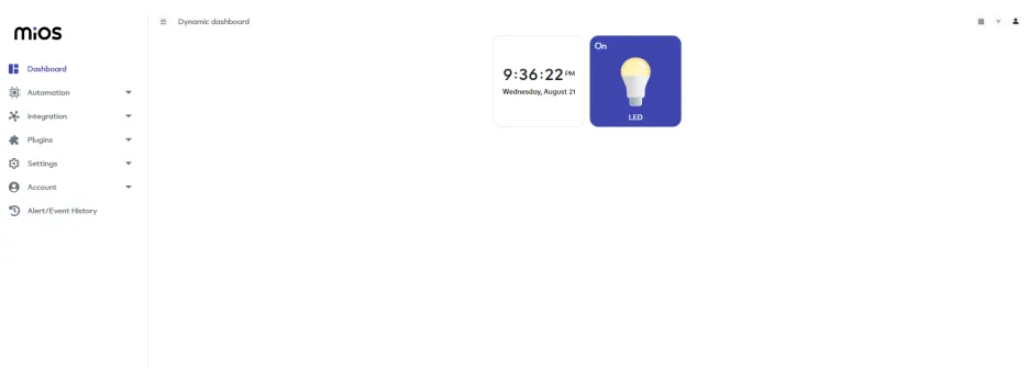
- Now, we can see that the conductive pen works as a wire, the state of the LED is controlled by drawing wires by the conductive pen.


