


The EzloPi smart devices provide automation through simple, customizable use with our open-source EzloPi platform, making daily life easier and improving human-machine interactions.
Before moving into this example, it is very important to know about the device registration, provisioning and converting the ESP32 device into an EzloPi device along with knowledge of Web Flasher, MiOS Mobile Application for Android/iOS and the MiOS Web Application.
1. About this example
In this project, the ACS712 current sensor is interfaced with the EzloPi device to enable automated power control. The ACS712 measures real-time current flow, allowing the EzloPi device to monitor power usage for various connected appliances. Based on the current threshold set in the EzloPi's device, the designed system can automatically control relays to switch appliances on or off, optimizing power consumption. This setup is useful for energy management, preventing overloads, and enhancing safety by detecting unusual current levels or faults. The project aims to create an efficient, automated, and scalable power management solution.
3. Circuit Diagram & Interface
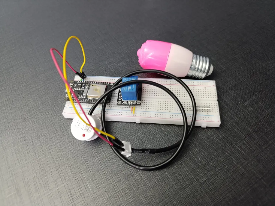
The following components are required for interfacing with the EzloPi device:
- ESP32 as an EzloPi smart device.
- ACS712 Current sensor.
- Single channel relay module.
- AC Lamp
- 220 Power source
The wiring diagram of ESP32 30 pin is represented as follows:
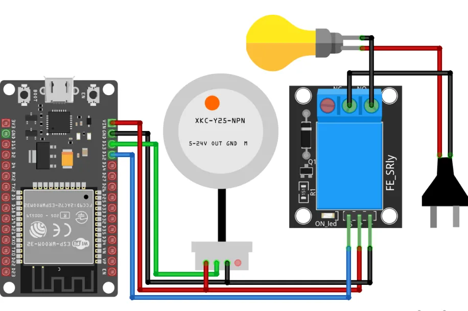
The following connections are made in order to complete the circuit setup.
From ESP32 to the ACS712:
| ESP32 | ACS712 |
| VIN | VCC |
| GND | GND |
| D33 | OUT |
From ESP32 to the Relay:
| ESP32 | Relay |
| VIN | +(VCC) |
| GND | -(GND) |
| D33 | S (Signal) |
From Relay to Bulb & 220AC Mains:
| Relay | Bulb | 220V |
| COM | NA | Neutral |
| NO | 1st Terminal | NA |
| NA | 2nd Terminal | Phase |
4. Interfacing the Current Sensor & Relay using the EzloPi Web Flasher:
1. Set up your device/hardware by visiting config.ezlopi.com

- Log in using the credentials which you just set earlier while signing up.
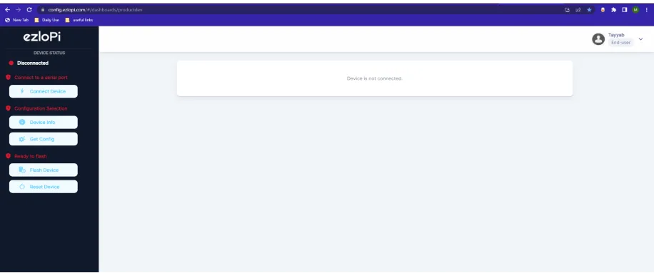
- Now, click on the Connect Device button and a pop-up window will appear.
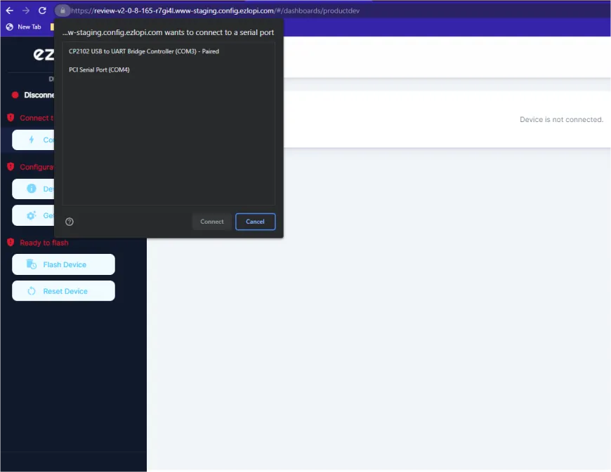
- Now, select COM Port to which your ESP32 device is connected. In our case, the COM3 port is used.
Click Connect
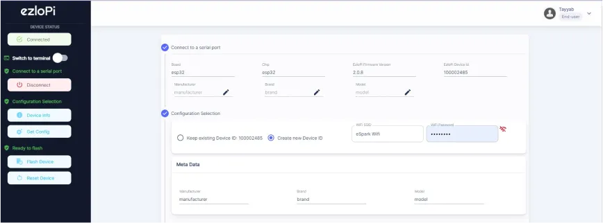
- If you are new to this and it's your first time configuring, select Create new Device ID. Enter Wifi SSID and Wifi Password.
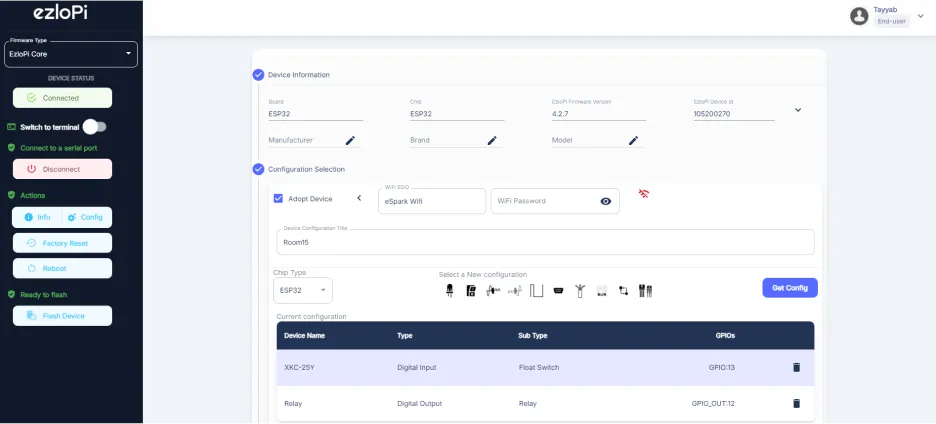
- In the Device Configuration, tab click on Analog Input.
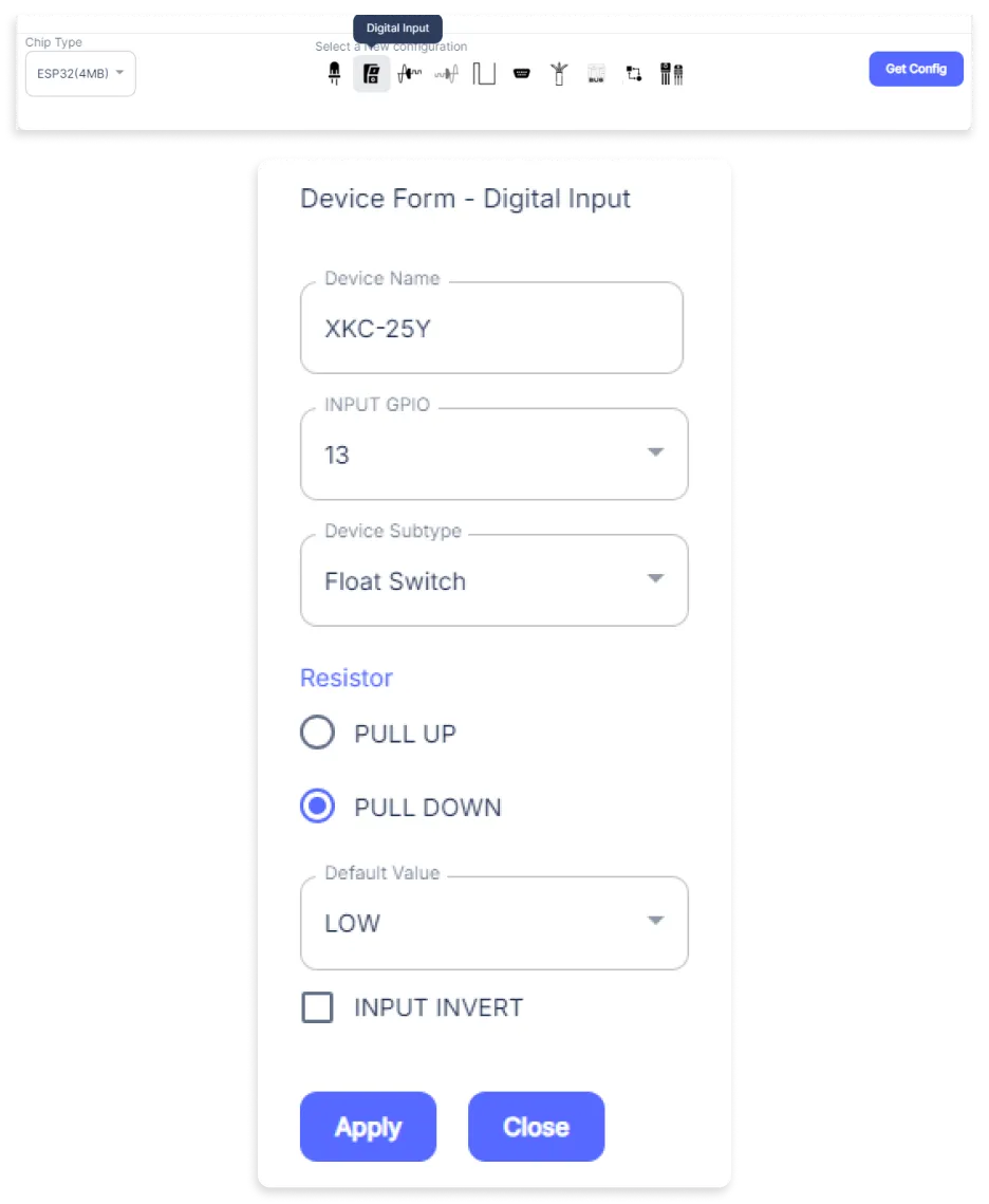
- An Analog Input window will open for inputting the following parameters:
- Set a Device Name of your choosing. In our case, we set it to Current Sensor.
- Set Device Subtype to CS712TELC 05B Current Sensor
- Set the ADC input pin to 33.
- Set the Resolution to 10-bit.
- Then Click Apply Button.
- In the Device Configuration, tab click on Digital Output.
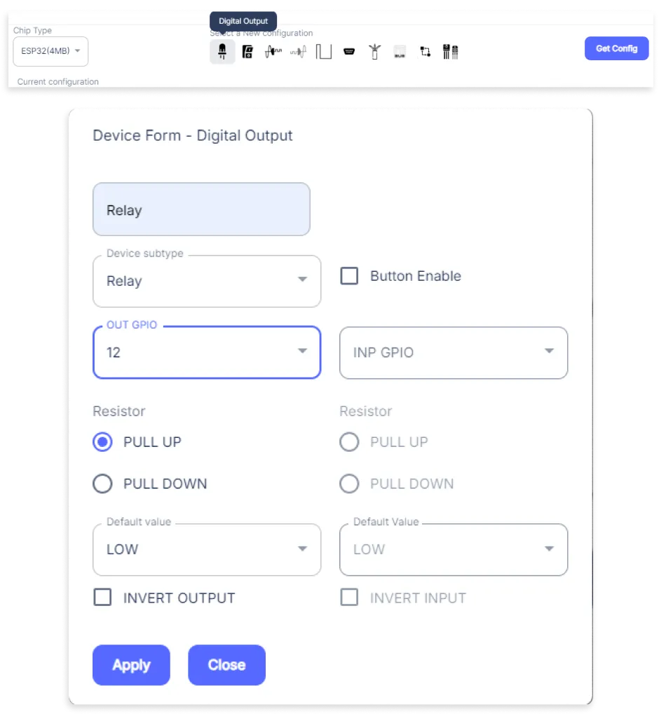
- A Digital Output window will open for inputting the following parameters:
- Set a Device name of your choosing. In our case, we set it to the Relay.
- Set Device Subtype to Relay.
- Set the OUT GPIO to 13.
- Set the Resistor to PULL UP.
- Then Click Apply Button.
- After clicking the apply button you can see a table of your setting in the device configuration tab.
- Press the Flash Device button.
- A window will appear on the bottom right side of the screen displaying “Please press BOOT button while flashing begins.”
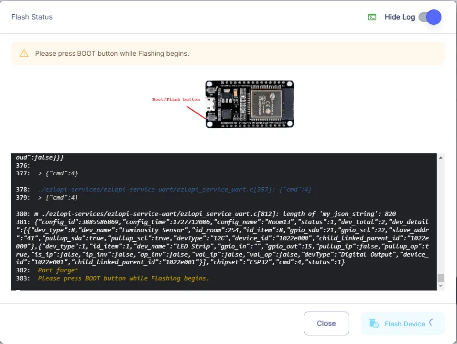
- Hold the BOOT button down until the next window appears on the bottom right side of the screen which says “Installation prepared. Please release the boot button now.”
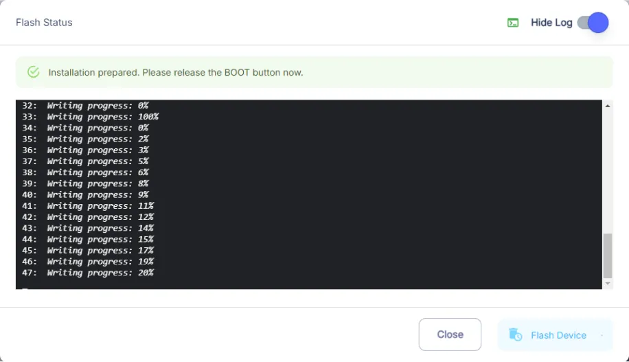
- Release the BOOT button from your ESP32 when this pop-up on the bottom right window appears.
- After some time, a popup will appear saying Device Flashed Successfully! This means that your device has been set up successfully.
5. MiOS Web Dashboard
- After configuring the controller with the EzloPi web flasher, head to ezlogic.mios.com

- Use the same credential to log in that you used for configuring the controller with the web flasher.
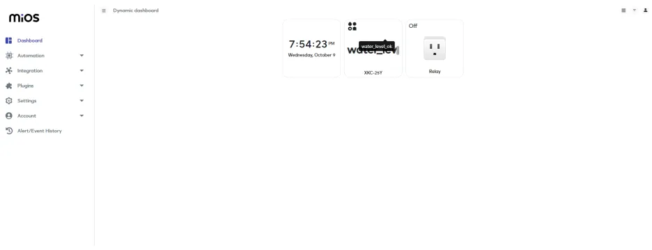
- Here, on the MiOS web dashboard, you will be able to see the tiles of connected devices. In our case we have an ACS712 current sensor and relay tiles. The relay tile will indicate the status of the current sensor whether or not the current within the set threshold.
MeshBots:
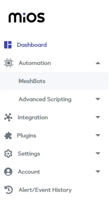
- On the left side of the screen under Automation, click on MeshBots.
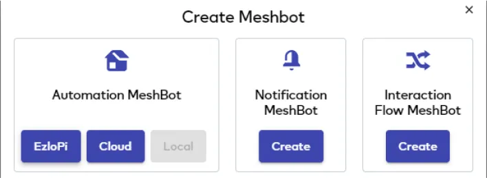
- On meshbot screen, click on Create new MeshBot button present on the top right corner of the screen.
- After clicking on Create new MeshBot, you will see this now under Automation MeshBot click on Local.
- On the next screen you will see that we can create a name of our choosing, in this case we write it as Test002.
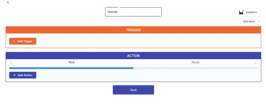
- In the trigger tab you can set the TRIGGER for your device and in the ACTION tab you can set the action to be performed based on the trigger which you have created.
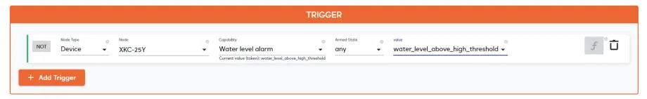
- Set these things in TRIGGER section:
- Set Node Type to Device.
- Set the Node to Current Sensor.
- Set the Capability to parent_abstract.
- Set the variables to uuid.
- Set the Comparator to Greater(>).
- Set the Value Type to value.
- Set the value to 3A.
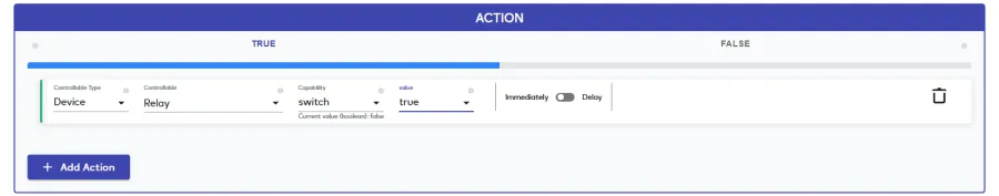
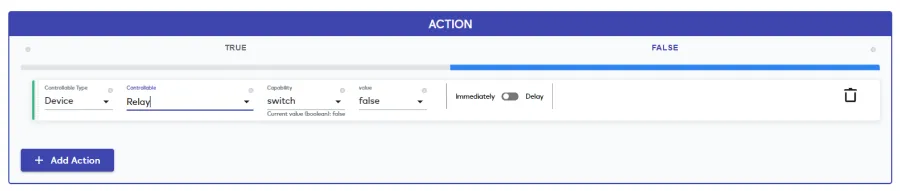
- Set these values in the TRUE part of the ACTION section.
- Set these values in the TRUE part of the ACTION section.
- Set Controllable Type to Device.
- Set the Controllable to Relay.
- Set the Capability to power_command.
- Set the Value Type to set.
- Set the Value to false.
- Now Click the Save button.
- After clicking the save button you can see this screen on the top right corner of the screen.

- Here you can see your saved MeshBot. Now click on Dashboard.

- Now in the MiOS web dashboard, we can see that when the current passing through current sensor is normal value and in our range, our relay is ON to and allow the current to pass through to the circuit according to the condition set in the meshbot.
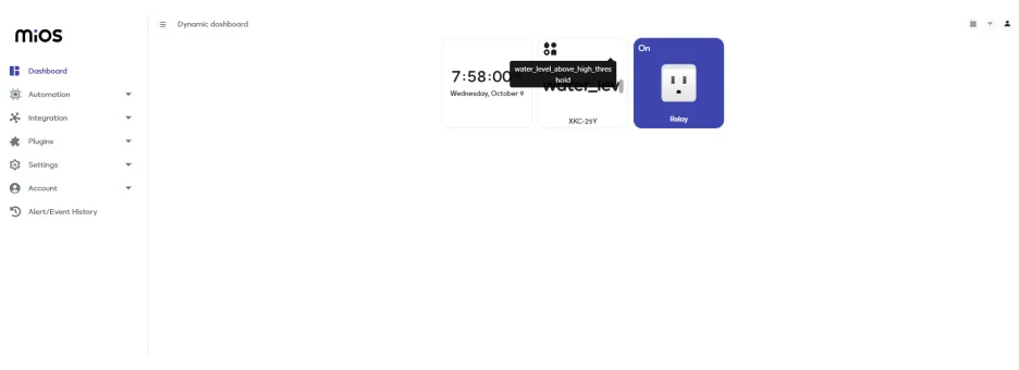
- Here in the above picture, it shows that when the current is out of limit and above our range then the relay turns OFF because of our meshbot setting to protect our whole circuit.
6. MiOS App
You can download the MIOS Android app from the Google Play Store and Apple App Store.


- After downloading the app, proceed to install the application and open it.

- Using the MIOS mobile application, create a new Ezlo Cloud account using the sign-up option. If you already have an account, you may proceed to log in.

- After successfully logging in, you will be able to see the number of controllers connected such as a lamp, fan, or any other device in the MiOS app. Tap on any controller of your desired ID:
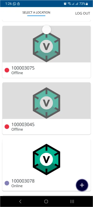
- You will be able to see the status of your controller whether it is online or offline. Access the device dashboard, and tap the device. The following view of the dashboard will appear:
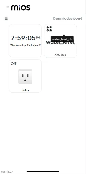
- On the MiOS mobile dashboard, we can see that when the current passing through current sensor is normal value and in our range, our relay is ON to and allow the current to pass through to the circuit according to the condition set in the meshbot.
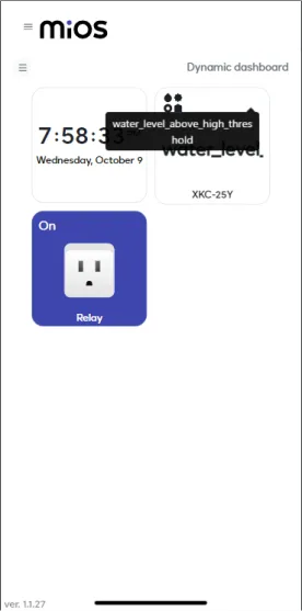
- Here in the above picture, it shows that when the current is out of limit and above our range then the relay turns OFF because of our meshbot setting to protect our whole circuit.


