The EzloPi smart devices provide automation through simple, customizable use with our open-source EzloPi platform, making daily life easier and improving human-machine interactions.
Before moving into this example, it is very important to know about the device registration, provisioning and converting the ESP32 device into an EzloPi device along with knowledge of Web Flasher, MiOS Mobile Application for Android/iOS and the MiOS Web Application..
1. About this example
This project aims to demonstrate how we can interface the soil moisture and humidity sensor with the EzloPi device to transform the sensor into a smart device for measuring the water levels or moisture levels of the soil for optimal growth of the plants. By interfacing the sensor with the EzloPi device, we can remotely monitor the moisture levels of the soil through the MiOS user-friendly interface. This integration can allow for automated watering systems, providing an efficient and convenient way to maintain optimal soil conditions for plants.
2. Project Demonstration Video
Welcome to the project demonstration video section. The following video showcases the key aspects of How to detect the soil moisture levels using HD-38 soil moisture sensor, providing a visual walkthrough of its implementation.
3. Circuit Diagram & Interface
The following components are required for interfacing using the EzloPi device:
- ESP32 as EzloPi smart device.
- HD-38 Soil moisture and humidity sensor module.
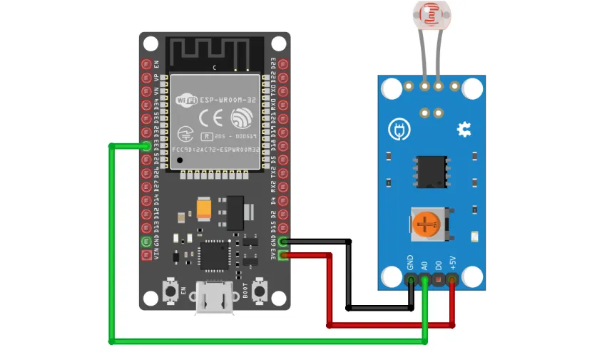
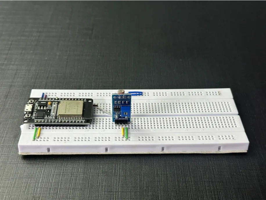
The wiring diagram is represented as follows:
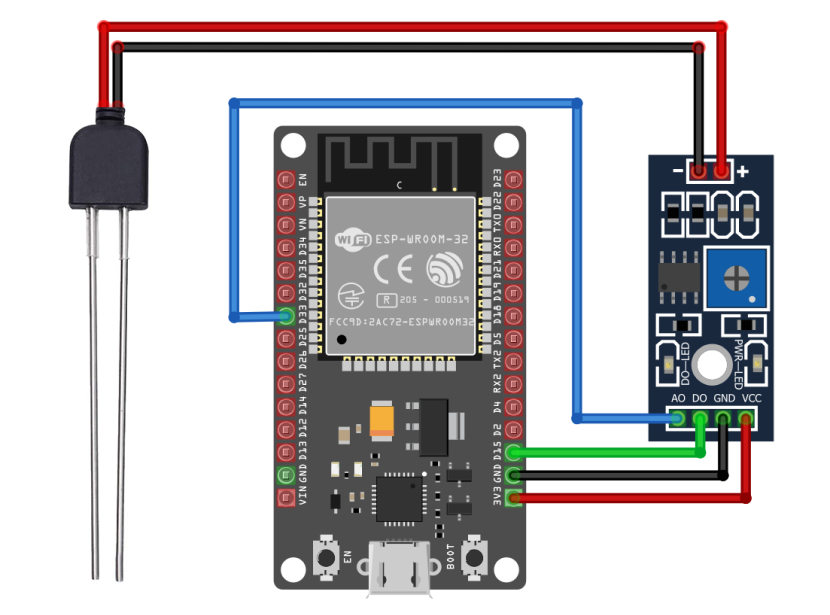
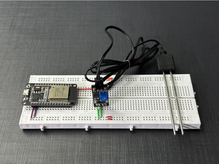
The following connections are made in order to complete the entire circuit setup:
From ESP32 to the HD-38 Soil moisture & Humidity Sensor Module:
| ESP32 | HD-38 module |
| 3V3 | VCC |
| GND | GND |
| D15 | DO |
| D33 | AO |
From ESP32 to the HD-38 Soil moisture & Humidity Sensor Module:
| HD-38 module | Sensor probe |
| + | 1st terminal |
| - | 2nd terminal |
4. Interfacing the LDR sensor module using EzloPi Web Flasher
1. Set up your device/hardware by visiting config.ezlopi.com

- Log in using the credentials which you just set earlier while signing up.
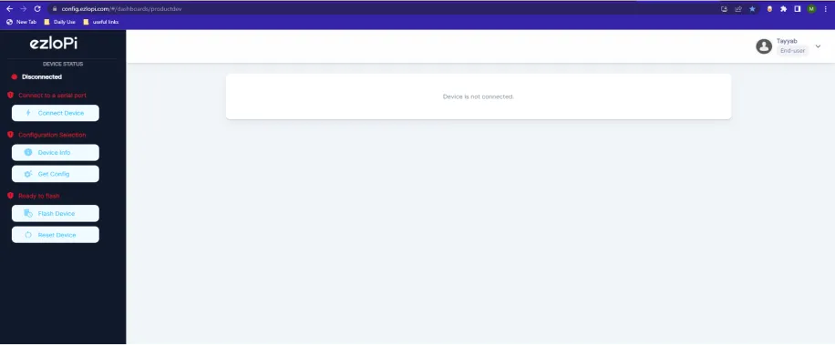
- Now, click on the Connect Device button and a pop-up window will appear.
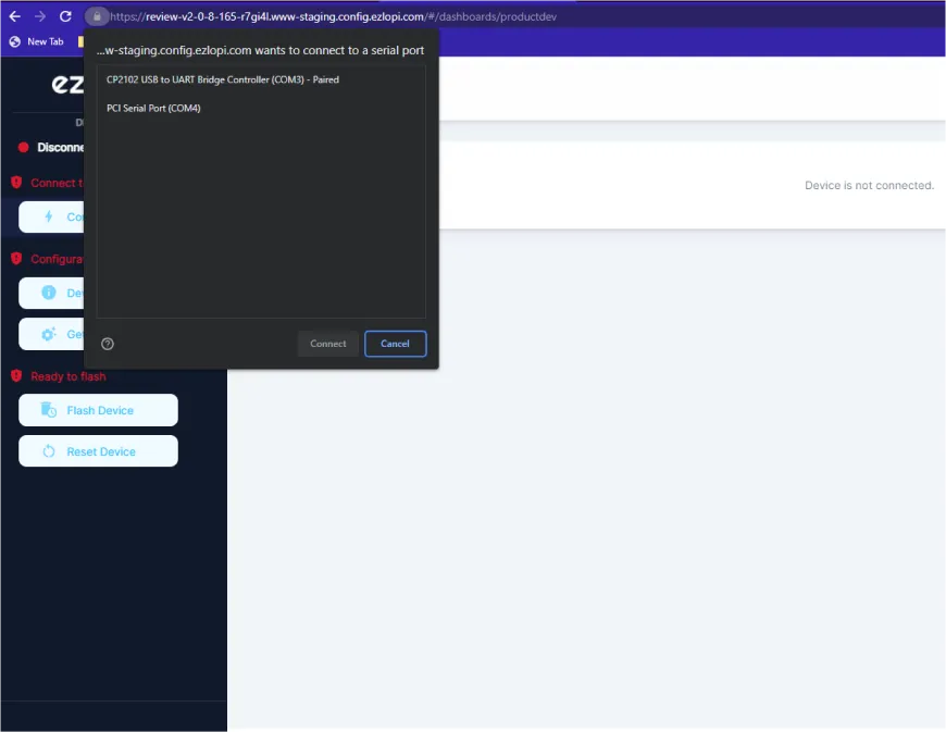
Now, select COM Port to which your ESP32 device is connected. In our case, the COM3 port is used.
Click Connect.
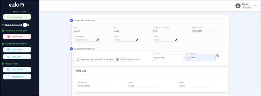
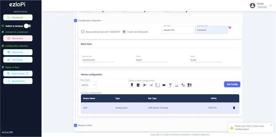
- If you are new to this and it's your first time configuring, select Create new Device ID. Enter Wifi SSID and Wifi Password.
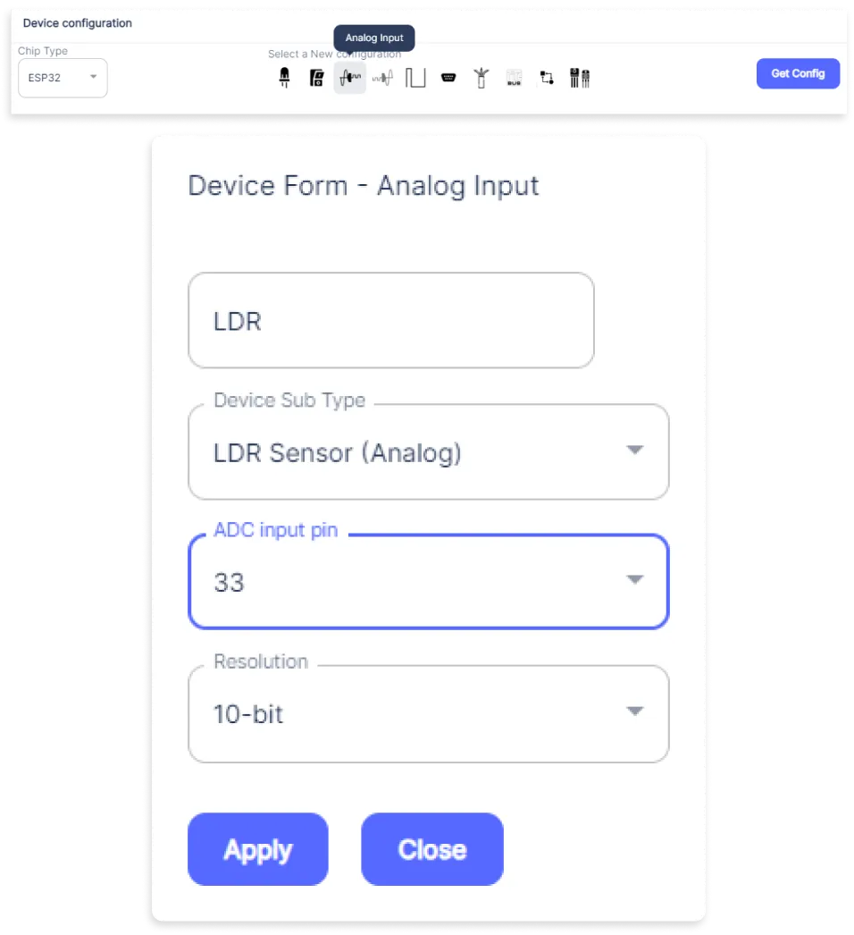
- In the Device Configuration, tab click on Analog Input.
- A Digital Input window will open for inputting the following parameters:
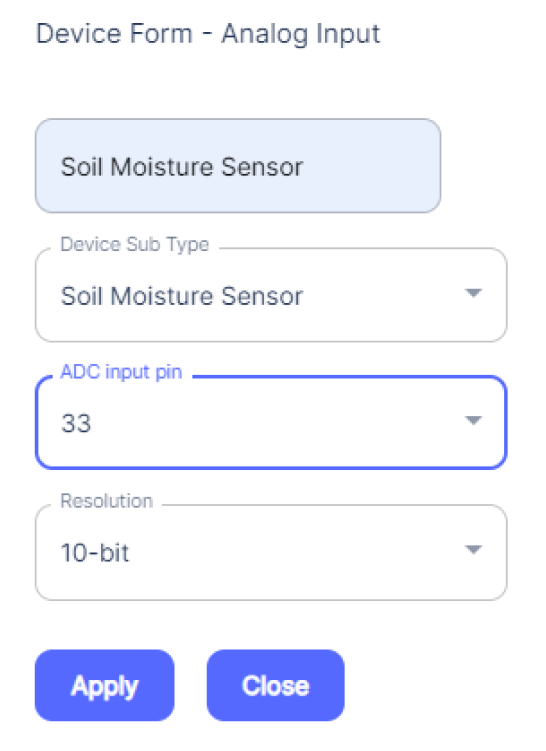
- An Analog Input window will open for inputting the following parameters:
- Set a device name of your choosing. In our case we set it to Soil Moisture Sensor.
- Set the Device Sub Type to Soil Moisture Sensor.
- Set the ADC input pin to 33.
- Then Click Apply Button.
- After clicking the apply button you can see a table of your setting in the device configuration tab.
- Press the Flash Device button.
- A window will appear on the bottom right side of the screen displaying “Please press BOOT button while flashing begins.”
- Hold the BOOT button down until the next window appears on the bottom right side of the screen which says “Installation prepared. Please release the boot button now.”
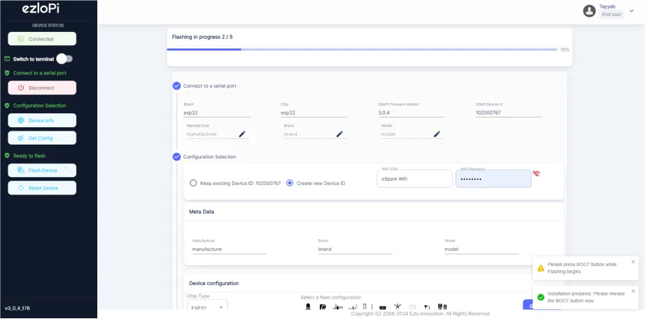
- Release the BOOT button from your ESP32 when this pop-up on the bottom right window appears.
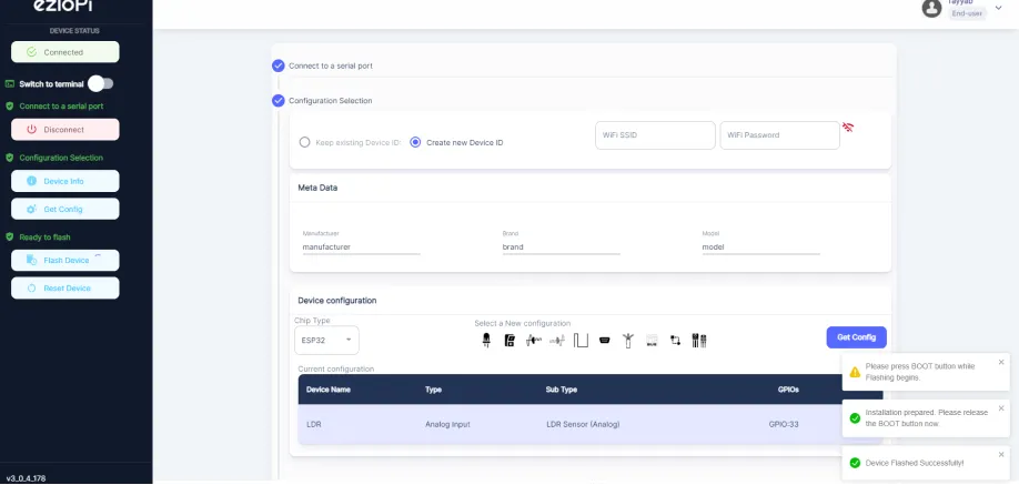
- After some time, a popup will appear saying Device Flashed Successfully! This means that your device has been set up successfully.
5. MiOS App
You can download the MIOS Android app from the Google Play Store and Apple App Store.


- After downloading the app, proceed to install the application and open it.

- Using the MIOS mobile application, create a new Ezlo Cloud account using the sign-up option. If you already have an account, you may proceed to log in.

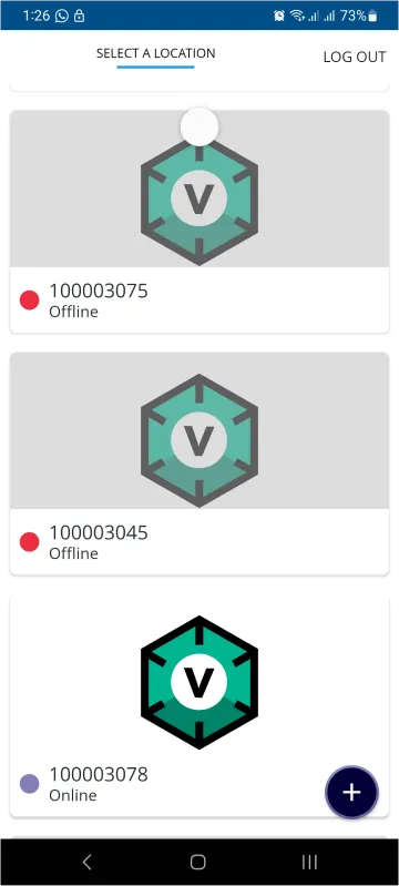
- After successfully logging in, you will be able to see the number of controllers connected such as a lamp, fan, or any other device in the MiOS app. Tap on any controller of your desired ID:
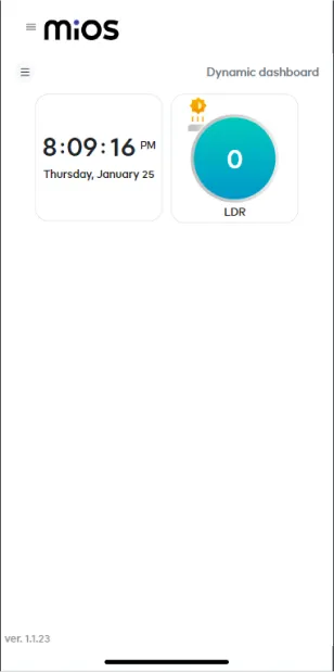
- You will be able to see the status of your controller whether it is online or offline. Access the device dashboard, and tap the device. The following view of the dashboard will appear:
- After opening the dashboard, you will be able to see the tile of your connected device.
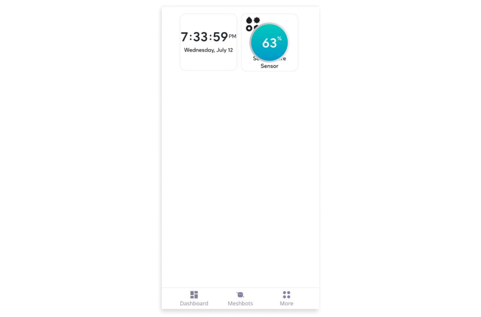
- After opening the MiOS mobile app, we can see the moisture sensor tile which shows the amount of moisture in the soil.
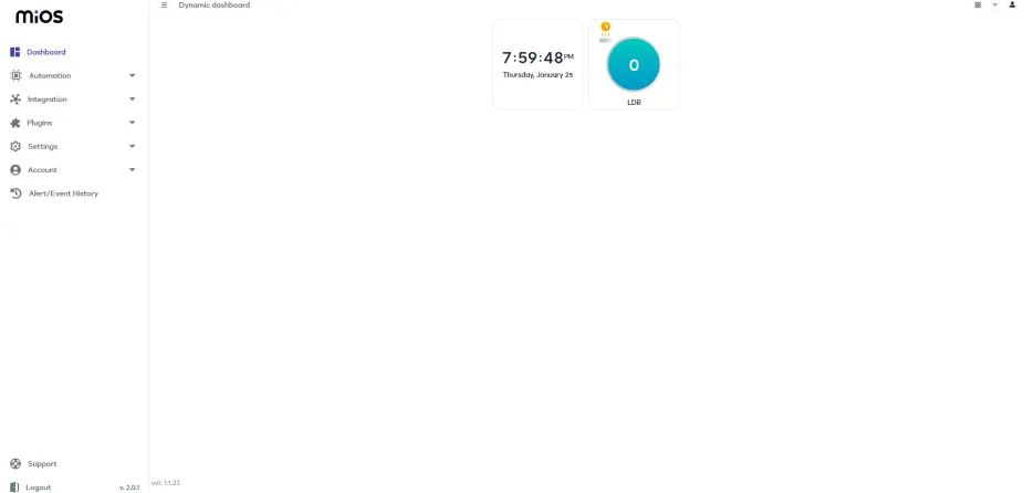
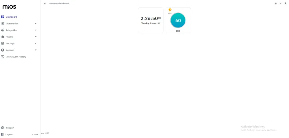
6. MiOS Web Application
- After configuring the controller with the EzloPi web flasher, head to ezlogic.mios.com

- Use the same credential to log in that you used for configuring the controller with the web flasher.

- After opening the MiOS web dashboard, we can see the moisture sensor tile which shows the amount of moisture in the soil.