


The EzloPi smart devices provide automation through simple, customizable use with our open-source EzloPi platform, making daily life easier and improving human-machine interactions.
Before moving into this example, it is very important to know about the device registration, provisioning and converting the ESP32 device into an EzloPi device along with knowledge of Web Flasher, MiOS Mobile Application for Android/iOS and the MiOS Web Application.
1. About this example
The smart aquarium management system project leverages the EzloPi device to monitor water levels using a P45 float switch. When the water level drops below a set threshold, the float switch triggers an LED indicator to alert the users. This simple, yet effective system ensures timely intervention for maintaining the correct water level, enhancing the safety and health of aquatic life in the aquarium. The project can be expanded to integrate additional sensors and controls, providing automated solutions for water refilling and other aquarium management tasks.
2. Project Demonstration Video
Welcome to the project demonstration video section. The following video showcases the key aspects of Automated aquarium management system, providing a visual walkthrough of its implementation.
3. Circuit Diagram & Interface
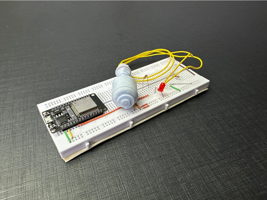
The following components are required for interfacing with the EzloPi device:
- ESP32 as an EzloPi smart device.
- P45 float switch.
- LED with 100 Ohm Resistor.
The wiring diagram of ESP32 30 pin is represented as follows:
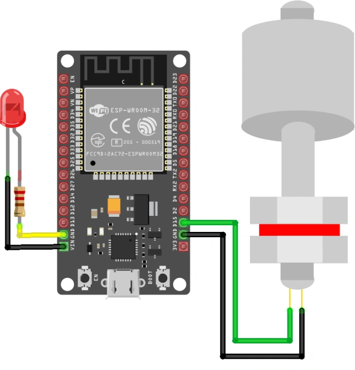
The following connections are made in order to complete the circuit setup.
From ESP32 to the Float Switch:
| ESP32 | Float Switch |
| GND | 1st Terminal |
| D4 | 2nd Terminal |
From ESP32 to the LED:
| ESP32 | LED | Resistor |
| D13 | - | Terminal no.1 |
| GND | Cathode | - |
| - | Anode | Terminal no.2 |
4. Interfacing the Float Switch and LED using the EzloPi Web Flasher
1. Set up your device/hardware by visiting config.ezlopi.com

- Log in using the credentials which you just set earlier while signing up.
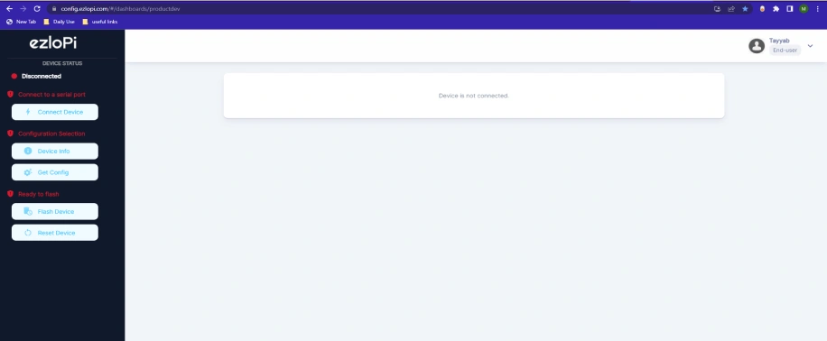
- Now, click on the Connect Device button and a pop-up window will appear.
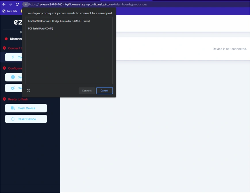
- Now, select COM Port to which your ESP32 device is connected. In our case, the COM3 port is used.
Click Connect
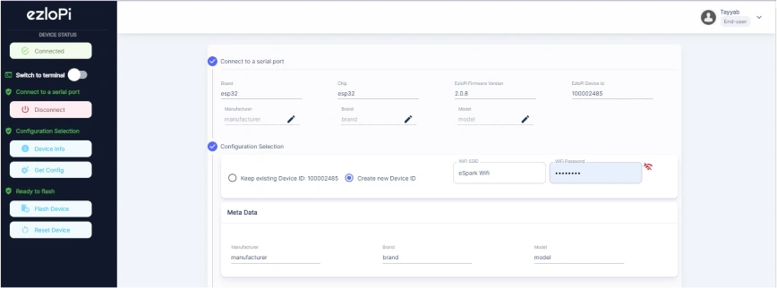
- If you are new to this and it's your first time configuring, select Create new Device ID. Enter Wifi SSID and Wifi Password.
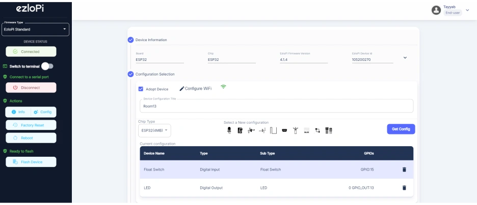
- In the Device Configuration, tab click on Digital Input.
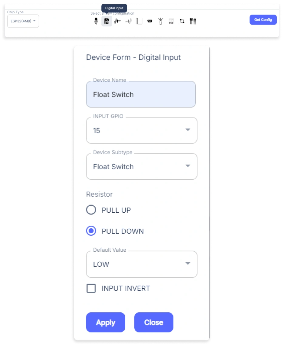
- A window will be opened for inputting the following parameters:
- Set a Device Name of your choosing. In our case, we will set it to Float Switch.
- Set INPUT GPIO to 15.
- Set the Device Subtype to Float Switch.
- Set the Resistor to PULL DOWN.
- Then Click Apply Button.
- In the Device Configuration, tab click on Digital Output.
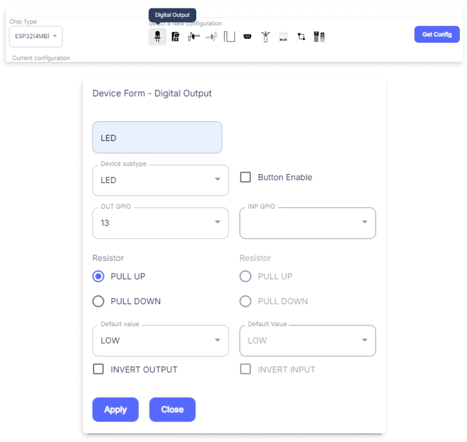
- A window will be opened for inputting the following parameters:
- Set a Device Name of your choosing. In our case, we will set it to LED.
- Set the Device Subtype to LED.
- Set OUT GPIO to 13.
- Set the Resistor to PULL UP.
- Then Click Apply Button.
- After clicking the apply button you can see a table of your setting in the device configuration tab.
- Press the Flash Device button.
- A window will appear on the bottom right side of the screen displaying “Please press BOOT button while flashing begins.”
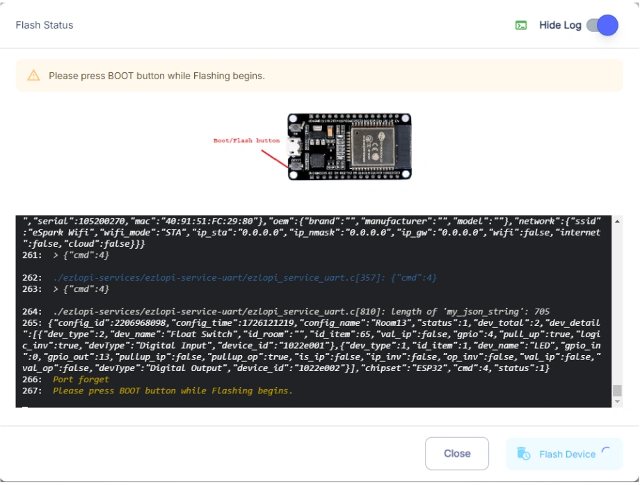
- Hold the BOOT button down until the next window appears on the bottom right side of the screen which says “Installation prepared. Please release the boot button now.”
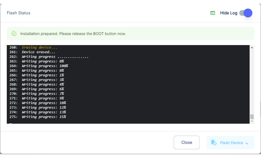
- Release the BOOT button from your ESP32 when this pop-up on the bottom right window appears.
- After some time, a popup will appear saying Device Flashed Successfully! This means that your device has been set up successfully.
5. MiOS Web Dashboard
- After configuring the controller with the EzloPi web flasher, head to ezlogic.mios.com

- Use the same credential to log in that you used for configuring the controller with the web flasher.
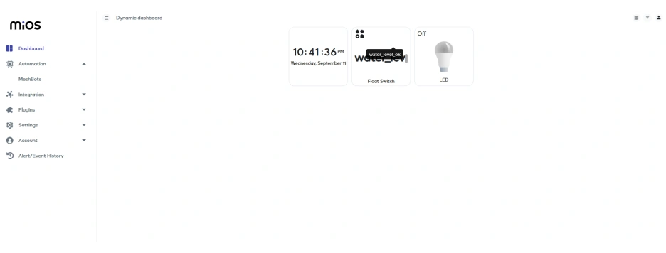
- Now, on the MiOS web dashboard, you will see the tiles of your connected devices as shown above labeled as Float switch and LED. Currently, the float switch tile shows “water_level_ok message” while LED shows OFF status.
MeshBots:
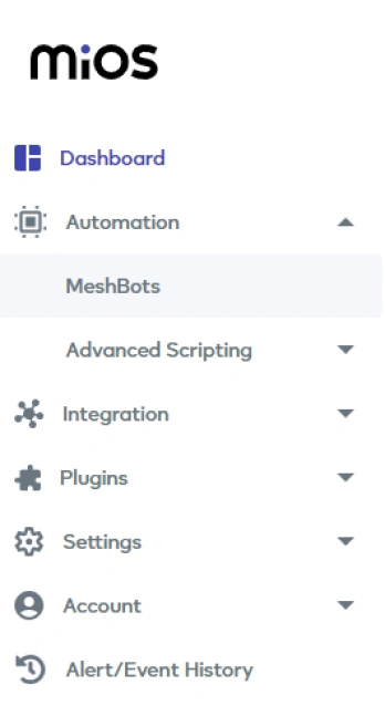
- On the left side of the screen under Automation, click on MeshBots.
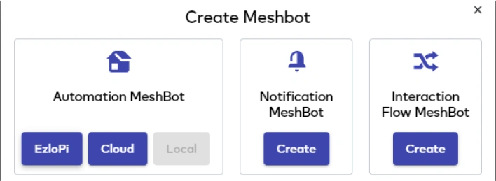
- On meshbot screen, click on Create new MeshBot button present on the top right corner of the screen.
- After clicking on Create new MeshBot, you will see this now under Automation MeshBot click on EzloPi.
- On the next screen you will see that we can create a name of our choosing, in this case we write it as Test002.
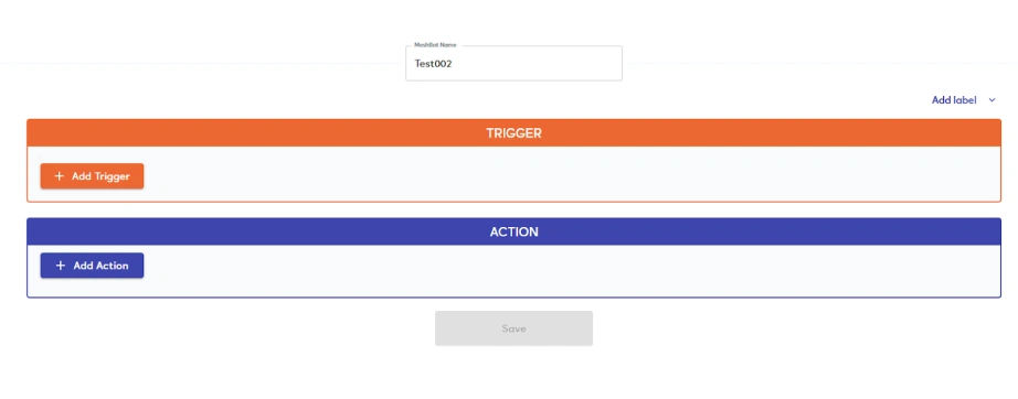
- In the trigger tab you can set the TRIGGER for your device and in the ACTION tab you can set the action to be performed based on the trigger which you have created.
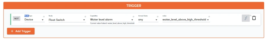
- Set these things in TRIGGER section:
- Set Node Type to Device.
- Set the Node to Float Switch.
- Set the Capability to Water level alarm.
- Set the Armed State to any.
- Set the value to water_level_above_high_threshold.
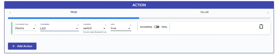
- Set these values in the TRUE part of the ACTION section.
- Set Node type to Device.
- Set Controllable to LED.
- Set Capability to switch.
- Set Value to true.
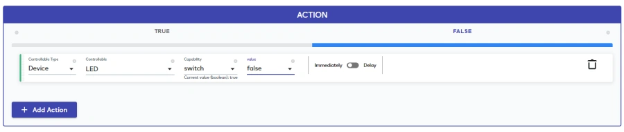
- Set these values in the FALSE part of the ACTION section.
- Set Node type to Device.
- Set Controllable to LED.
- Set Capability to switch.
- Set Value to false.
- After clicking the apply button you can see a table of your setting in the Current configuration tab.

- After clicking the save button you can see this screen on the top right corner of the screen.
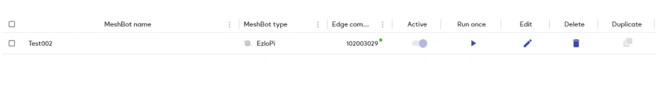
- Here you can see your saved MeshBot. Now click on Dashboard.
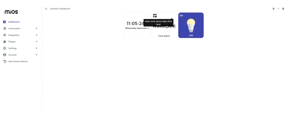
- Now in the above picture, It shows that when water level goes below our required limit in the aquarium then the LED will turn ON. We can also use a motor instead of the LED so that when water level decreases then the motor pumps the water into the aquarium tank according to rules we have set in the meshbot.
6. MiOS App
You can download the MIOS Android app from the Google Play Store and Apple App Store.


- After downloading the app, proceed to install the application and open it.

- Using the MIOS mobile application, create a new Ezlo Cloud account using the sign-up option. If you already have an account, you may proceed to log in.

- After successfully logging in, you will be able to see the number of controllers connected such as a lamp, fan, or any other device in the MiOS app. Tap on any controller of your desired ID:
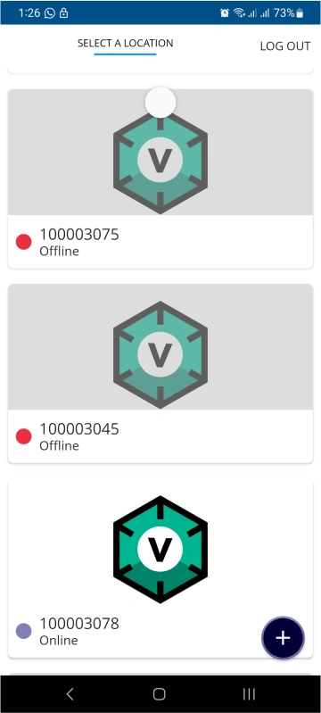
- You will be able to see the status of your controller whether it is online or offline. Access the device dashboard, and tap the device. The following view of the dashboard will appear:
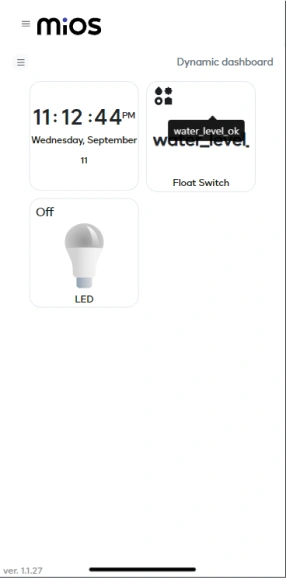
- Now, on the MiOS mobile dashboard, you will see the tiles of your connected devices as shown above labeled as Float switch and LED. Currently, the float switch tile shows “water_level_ok message” while LED shows OFF status.

- Now in the above pic, It shows that when water level goes below our required limit in the aquarium then the LED will turn ON. We can also use a motor instead of the LED so that when water level decreases then the motor pumps the water into the aquarium tank according to rules we have set in the meshbot.


