The EzloPi smart devices provide automation through simple, customizable use with our open-source EzloPi platform, making daily life easier and improving human-machine interactions.
Before moving into this example, it is very important to know about the device registration, provisioning and converting the ESP32 device into an EzloPi device along with knowledge of Web Flasher, MiOS Mobile Application for Android/iOS and the MiOS Web Application.
1. About this example
This project aims to provide advanced light sensing capabilities enabling users to efficiently monitor ambient light levels in their surroundings. By interfacing the EzloPi device with the LTR303ALS sensor, users can enjoy seamless automation and smart control over lighting systems based on real-time luminosity data. The integration offers a versatile solution for various applications, including smart homes, industrial automation, and environmental monitoring.
Leveraging the EzloPi's robust platform and the precision of the LTR303ALS sensor, this project elevates the user experience by delivering accurate and responsive light sensing functionality and notifying the user about it. Through the MiOS app, users can remotely monitor the light intensity value in terms of lux which will be displayed on the MiOS application dashboard.
2. Project Demonstration Video
Welcome to the project demonstration video section. The following video showcases the key aspects of Light Intensity Measurement & Notification with the LTR303ALS Luminosity sensor, providing a visual walkthrough of its implementation.
3. Circuit Diagram & Interface
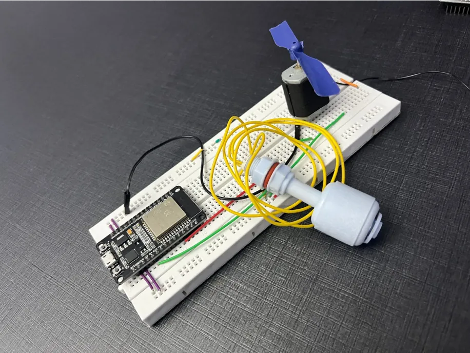
The following components are required for interfacing with the EzloPi device:
- ESP32 as an EzloPi smart device.
- LTR303ALS Luminosity sensor
The wiring diagram of ESP32 30 pin is represented as follows:
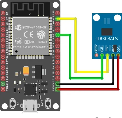
The following connections are made in order to complete the circuit setup.
From ESP32 to the LTR303ALS Luminosity sensor:
| ESP32 | LTR303ALS |
| 3V3 | VCC |
| GND | GND |
| D21 | SDA |
| D22 | SCL |
4. Interfacing the LDR sensor & Buzzer module using EzloPi Web Flasher
1. Set up your device/hardware by visiting config.ezlopi.com

- Log in using the credentials which you just set earlier while signing up.
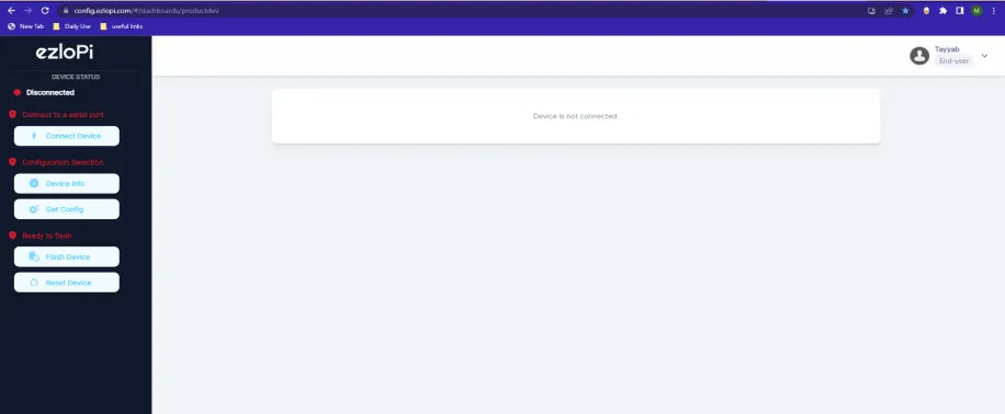
- Now, click on the Connect Device button and a pop-up window will appear.
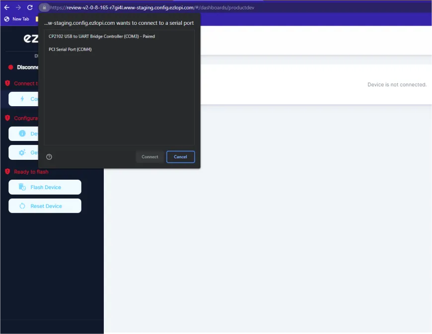
- Now, select COM Port to which your ESP32 device is connected. In our case, the COM3 port is used.
Click Connect
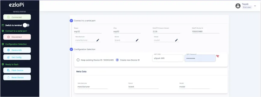
- If you are new to this and it's your first time configuring, select Create new Device ID. Enter Wifi SSID and Wifi Password.
- In the Device Configuration, tab click on I2C.
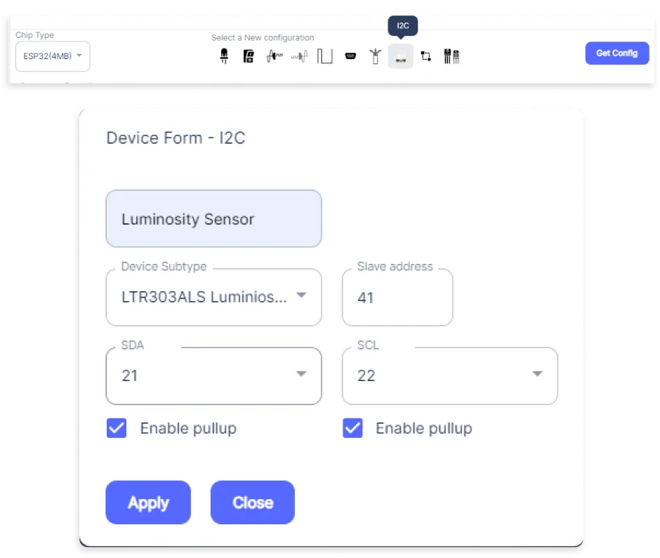
- A I2C window will open for inputting the following parameters:
- Set a device name of your choosing. In our case, we set it to Luminosity Sensor.
- Set Device subtype to LTR303ALS Luminosity Sensor.
- Set Slave address to 57.
- Set SDA pin to GPIO21.
- Set SCL pin to GPIO22.
- Mark both Enable pullup boxes.
- Then Click Apply Button.
- After clicking the apply button you can see a table of your setting in the device configuration tab.
- Press the Flash Device button.
- A window will appear on the bottom right side of the screen displaying “Please press BOOT button while flashing begins.”
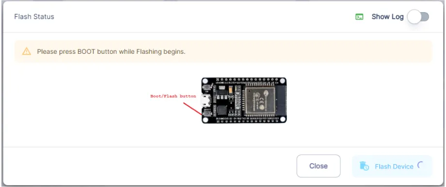
- Hold the BOOT button down until the next window appears on the bottom right side of the screen which says “Installation prepared. Please release the boot button now.”
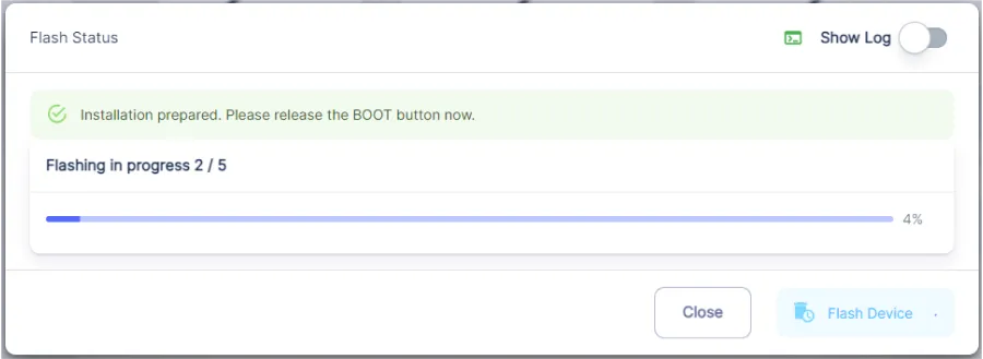
- Release the BOOT button from your ESP32 when this pop-up on the bottom right window appears.
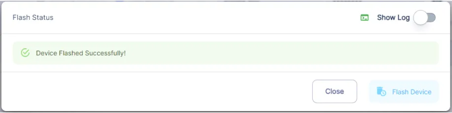
- After some time, a popup will appear saying Device Flashed Successfully! This means that your device has been set up successfully.
5. MiOS Web Dashboard
- After configuring the controller with the EzloPi web flasher, head to ezlogic.mios.com

- Use the same credential to log in that you used for configuring the controller with the web flasher.
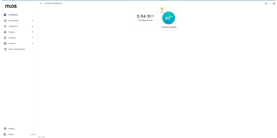
- Here as you can see above the LTR303ALS Luminosity sensor tile. The tile shows the Light intensity being detected by the sensor.
MeshBots:
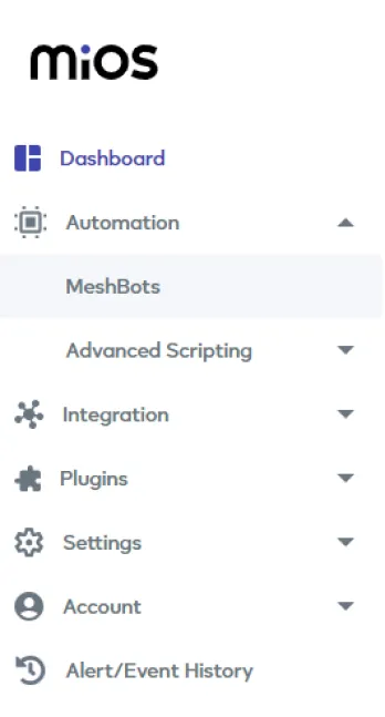
- On the left side of the screen under Automation, click on MeshBots.
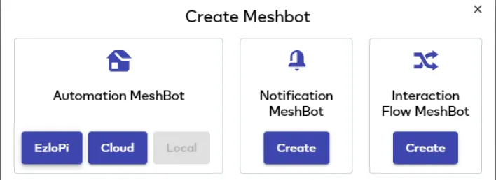
- On meshbot screen, click on Create new MeshBot button present on the top right corner of the screen.
- After clicking on Create new MeshBot, you will see this now under Notification MeshBot click on Cloud.
- On the next screen you will see that we can create a name of our choosing, in this case we write it as Test001.
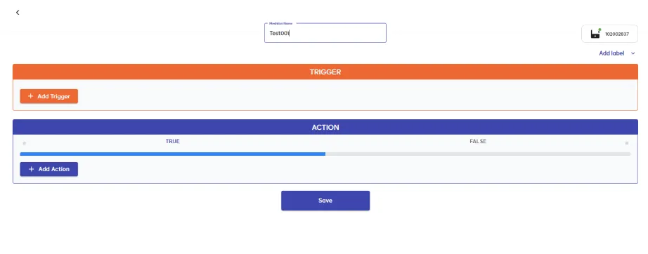
- In the trigger tab you can set the TRIGGER for your device and in the ACTION tab you can set the action to be performed based on the trigger which you have created.
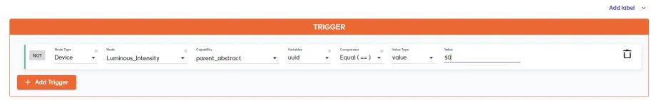
- Set these values in TRIGGER section:
- Set Node Type to Device.
- Set the Node to Luminous_intensity.
- Set the Capability to parent_abstract.
- Set the variables to uuid.
- Set the Comparator to Equal (==).
- Set the Value Type to value.
- Set the value to 50.
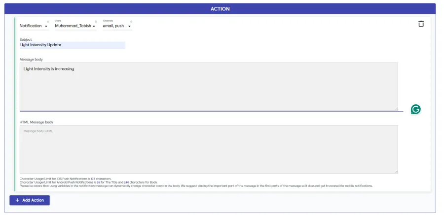
- Set these values in the ACTION section:
- Set Controllable Type to Notification.
- Set the User to Your user account but in our case the user account is Muhammad Tabish.
- Set the Channels to email,push.
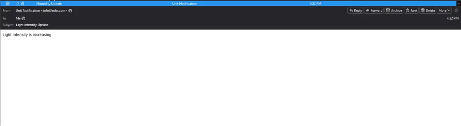
- Set the Subject to Light Intensity Update.
- Set the Message body info to Light intensity is increasing.
- After clicking the apply button you can see a table of your setting in the Current configuration tab.

- After clicking the save button you can see this screen on the top right corner of the screen.
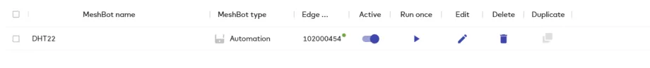
- Here, you can see your saved MeshBot. Now click on Dashboard.
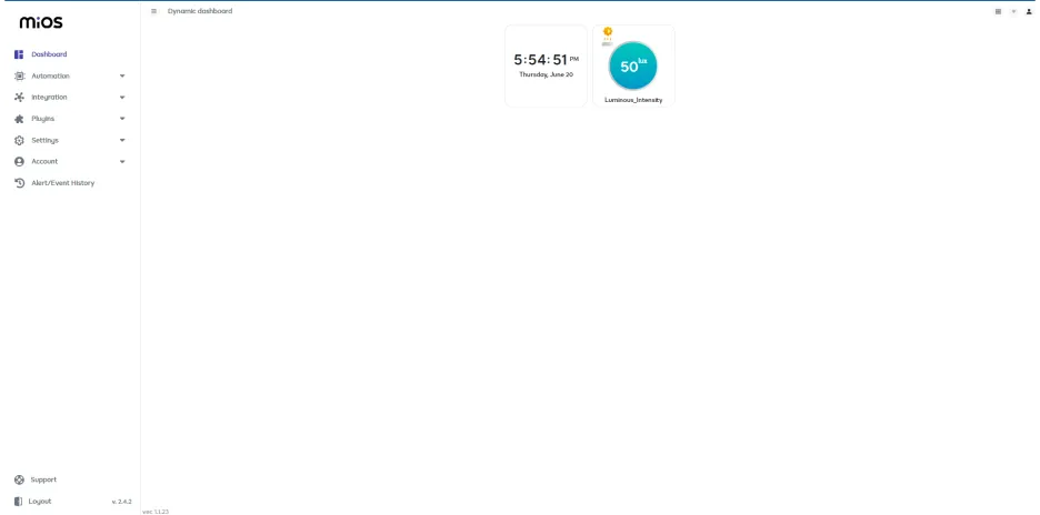
- Now, as you can see above, the Light intensity has increased to 50 which is the value at which notification to the user must be sent according to meshbot rules we have set.
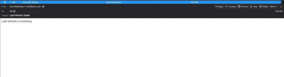
- In this scenario, an email is generated to the user’s gmail account which can be seen below.
6. MiOS App
You can download the MIOS Android app from the Google Play Store and Apple App Store.


- After downloading the app, proceed to install the application and open it.

- Using the MIOS mobile application, create a new Ezlo Cloud account using the sign-up option. If you already have an account, you may proceed to log in.

- After successfully logging in, you will be able to see the number of controllers connected such as a lamp, fan, or any other device in the MiOS app. Tap on any controller of your desired ID:
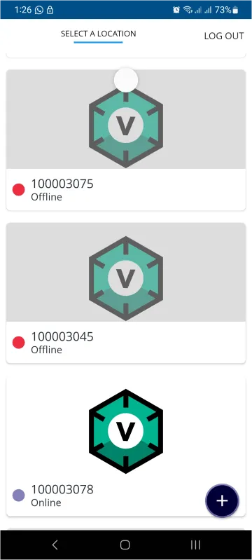
- You will be able to see the status of your controller whether it is online or offline. Access the device dashboard, and tap the device. The following view of the dashboard will appear:
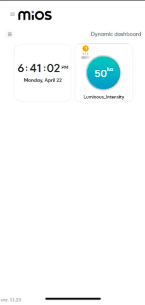
- Now, as you can see above, the Light intensity has increased to 50 which is the value at which notification to the user must be sent according to meshbot rules we have set.
- In this scenario, an email is sent to the user’s gmail account which can be seen below.