


The EzloPi smart devices provide automation through simple, customizable use with our open-source EzloPi platform, making daily life easier and improving human-machine interactions.
Before moving into this example, it is very important to know about the device registration, provisioning and converting the ESP32 device into an EzloPi device along with knowledge of Web Flasher, MiOS Mobile Application for Android/iOS and the MiOS Web Application.
1. About this example
The smart weather station project using the EzloPi device will monitor environmental conditions such as temperature, humidity, and atmospheric pressure and rain. The project will collect real-time sensor data and display it on the MiOS smart platform. The project is designed to work efficiently in various environments, potentially integrating features like wireless data transmission and local storage for weather history. The project aims to create an easily deployable and scalable weather monitoring solution utilizing the EzloPi smart IoT platform.
2. Project Demonstration Video
Welcome to the project demonstration video section. The following video showcases the key aspects of Smart greenhouse garden using soil moisture sensor, LDR and MQ135 sensor, providing a visual walkthrough of its implementation.
3. Circuit Diagram & Interface
The following components are required for interfacing with the EzloPi device:
- ESP32 as an EzloPi smart device.
- 5V BME280 Barometric pressure & humidity sensor.
- LM393 comparator IC module.
- FC-37 rain sensor module.
- LM393 based 4-pin photoresistor sensor module (LDR).
The wiring diagram for the ESP32 30 pin is represented as below:
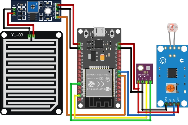
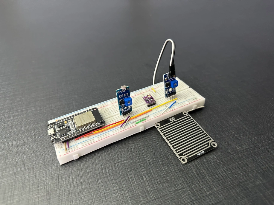
The following connections are made in order to complete the circuit setup:
From ESP32 to the BME280:
| ESP32 | BME80 |
| VIN | VIN |
| GND | GND |
| D21 | SCL |
| D22 | SDA |
From ESP32 to the LM393 comparator module:
| ESP32 | LM393 Comparator Module |
| VCC | VCC |
| GND | GND |
| D33 | A0 |
From the LM393 module to the Rain sensor:
| LM393 Comparator Module | Rain Sensor Module |
| Pin 1 | POS |
| Pin 2 | NEG |
From ESP32 to LDR Module:
| ESP32 | LDR Module |
| 3V3 | VCC |
| GND | GND |
| D25 | D0 |
4. Interfacing the Rain Sensor, LDR and pressure sensor with the EzloPi Web Flasher:
1. Set up your device/hardware by visiting config.ezlopi.com

- Log in using the credentials which you just set earlier while signing up.
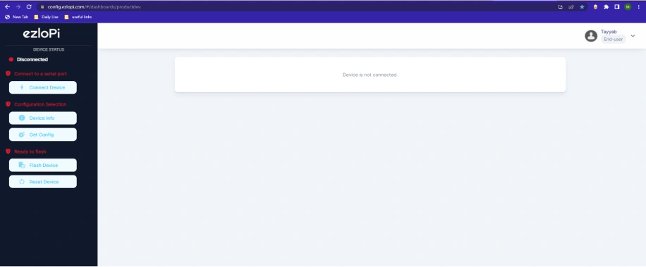
- Now, click on the Connect Device button and a pop-up window will appear.
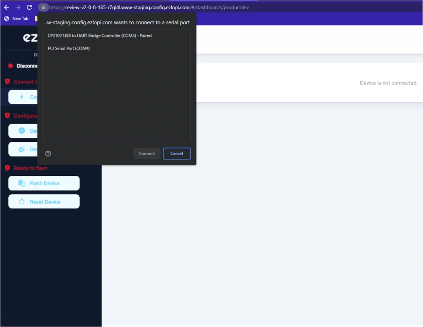
- Now, select COM Port to which your ESP32 device is connected. In our case, the COM3 port is used.
Click Connect
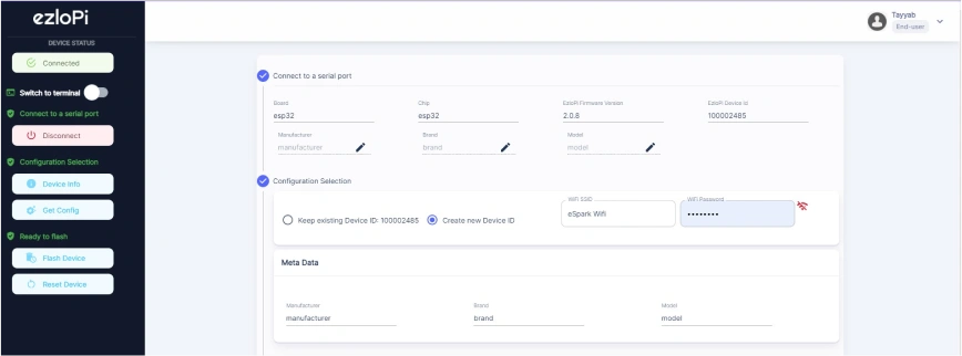
- If you are new to this and it's your first time configuring, select Create new Device ID. Enter Wifi SSID and Wifi Password.
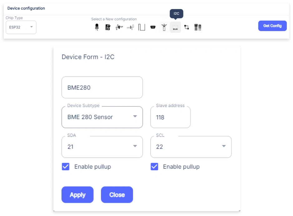
- In the Device Configuration, tab click on I2C.
- An Analog Input window will open for inputting the following parameters:
- A I2C Input window will open for inputting the following parameters:
- Set a Device name of your choosing. In our case, we set it to BME280.
- Set Device Subtype to BME 280 Sensor.
- Set the Slave Address to 118.
- Set the SDA pin to 21.
- Set the SCL pin to 22.
- Tick the “Enable Pullup” for both the SDA and SCL.
- Then Click Apply Button.
- Again, In the Device Configuration, tab click on Analog Input.

- An Analog Input window will open for inputting the following parameters:
- Set a Device name of your choosing. In our case, we set it to the Rain Sensor.
- Set Device Subtype to Water Leak Sensor.
- Set the ADC input pin to 33.
- Set the Resolution to 10-bit.
- Then Click Apply Button
- Again, In the Device Configuration, tab click on Digital Input.
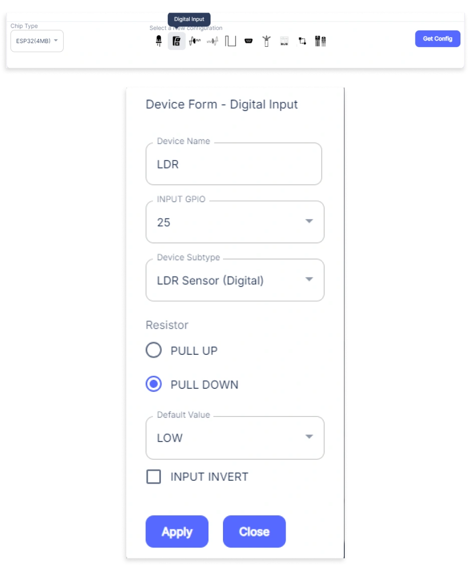
- A Digital Input window will open for inputting the following parameters:
- Set a Device name of your choosing. In our case, we set it to LDR.
- Set INPUT GPIO to 25.
- Set Device Subtype to LDR Sensor (Digital).
- Set Resistor to PULL UP.
- Set Default value to LOW.
- Then Click Apply Button.
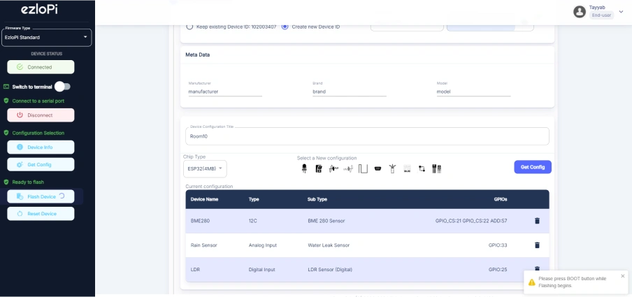
- After clicking the apply button you can see a table of your setting in the device configuration tab.
- Press the Flash Device button.
- A window will appear on the bottom right side of the screen displaying “Please press BOOT button while flashing begins.”
- Hold the BOOT button down until the next window appears on the bottom right side of the screen which says “Installation prepared. Please release the boot button now.”
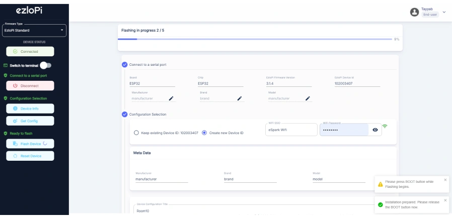
- Release the BOOT button from your ESP32 when this pop-up on the bottom right window appears.
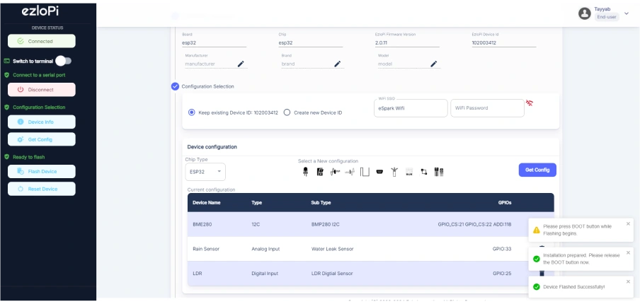
- After some time, a popup will appear saying Device Flashed Successfully! This means that your device has been set up successfully.
5. MiOS App
You can download the MIOS Android app from the Google Play Store and Apple App Store.


- After downloading the app, proceed to install the application and open it.

- Using the MIOS mobile application, create a new Ezlo Cloud account using the sign-up option. If you already have an account, you may proceed to log in.

- After successfully logging in, you will be able to see the number of controllers connected such as a lamp, fan, or any other device in the MiOS app. Tap on any controller of your desired ID:
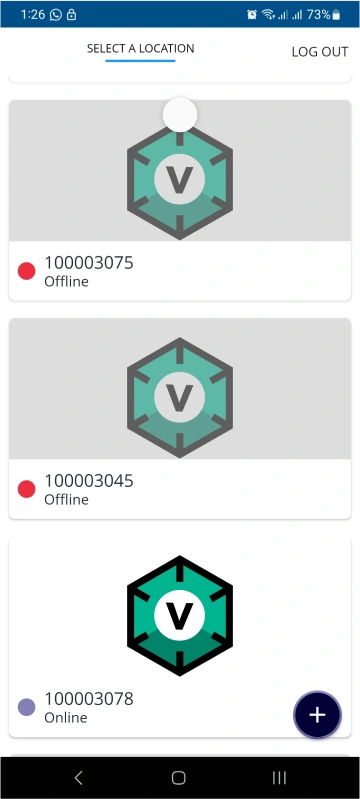
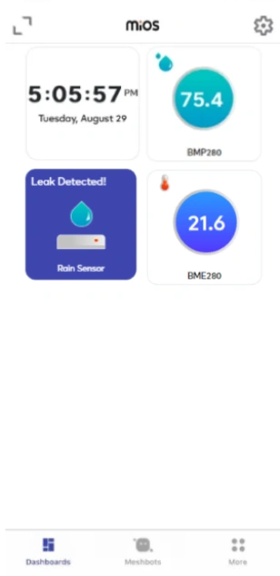
- You will be able to see the status of your controller whether it is online or offline. Access the device dashboard, and tap the device. The following view of the dashboard will appear:
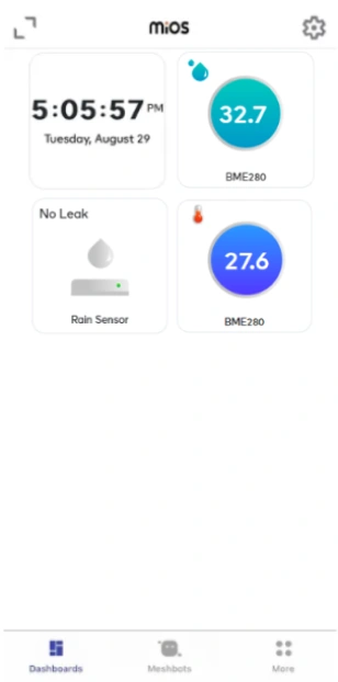
- After opening the MiOS web dashboard, you will be able to see the tiles of your connected devices. As we can see above, the BMP280 sensor module tile is showing the current humidity and temperature values, while the rain sensor shows the No rain or No leak message for now and the LDR sensor tile is ON because there is light present in the environment.
- Now, it is showing that it is raining so the humidity value has increased. The Rain sensor is detecting rain and the LDR is showing an OFF message because of low light in the environment.
6. MiOS Web Dashboard
- After configuring the controller with the EzloPi web flasher, head to ezlogic.mios.com

- Use the same credentials to log in that you used for configuring the controller with the web flasher.
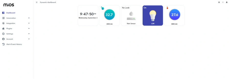
- After opening the MiOS mobile dashboard, you will be able to see the tiles of your connected devices. As we can see above, the BMP280 sensor module tile is showing the current humidity and temperature values, while the rain sensor shows the No rain or No leak message for now and the LDR sensor tile is ON because there is light present in the environment.
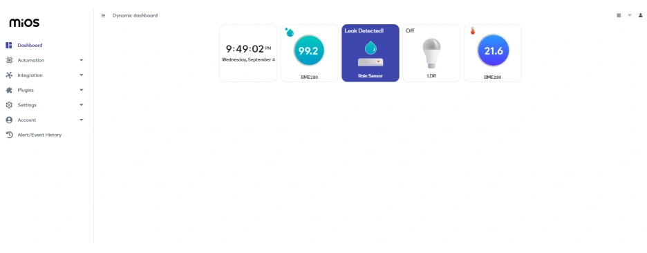
- Now, it is showing that it is raining so the humidity value has increased. The Rain sensor is detecting rain and the LDR is showing an OFF message because of low light in the environment.


