


BMP280 Pressure Sensor
The EzloPi smart devices provide automation through simple, customizable use with our open-source EzloPi platform, making daily life easier and improving human-machine interactions.
Before moving into this example, it is very important to know about the device registration, provisioning and converting the ESP32 device into an EzloPi device along with knowledge of Web Flasher, MiOS Mobile Application for Android/iOS and the MiOS Web Application.
1. About this example
The goal of this example is to elevate the capabilities of the EzloPi device by seamlessly integrating the BMP280 module, a cutting-edge environmental sensor. The BMP280 module offers high-precision measurements of temperature and pressure, enabling the EzloPi device to gather valuable data and provide real-time insights into the surrounding environment.
The BMP280-EzloPi interface offers an innovative solution for capturing precise environmental parameters for a wide range of applications, including weather monitoring, indoor climate control, altitude detection, and more. Users are also able to monitor real-time data with the help of the MiOS mobile app and web dashboard.
2. Circuit Setup & Interfacing
The following components are required for interfacing the BMP280 sensor module with the EzloPi device:
- ESP32 as EzloPi smart device.
- BMP280 Barometric Pressure & Altitude Sensor.
The wiring diagram of ESP32 32 pin is represented as follows:


The following connections are made in order to complete the entire circuit setup.
From ESP32 (32 pins) to the BMP280:
- Connect the GND from the ESP32 to the GND pin of the BMP280.
- Connect the 3v3 pin from the ESP32 to the VCC or VIN pin.
- Connect the D21 pin from the ESP32 to the serial data (SDA) pin on the BMP280.
- Connect the D22 pin from the ESP32 to the serial clock (SCL) pin on the BMP280.
The wiring diagram of ESP32 38 pin is also represented as below:

The following connections are made in order to complete the circuit setup.
From ESP32 (38 pins) to the BMP280:
- Connect the GND from the ESP32 to the GND pin of the BMP280.
- Connect the 3v3 pin from the ESP32 to the VCC or VIN pin.
- Connect the IO21 pin from the ESP32 to the serial data (SDA) pin on the BMP280.
- Connect the IO22 pin from the ESP32 to the serail clock (SCL) pin on the BMP280.
3. Interfacing the BMP280 Pressure Sensor using EzloPi Web Flasher
1. Set up your device/hardware by visiting config.ezlopi.com
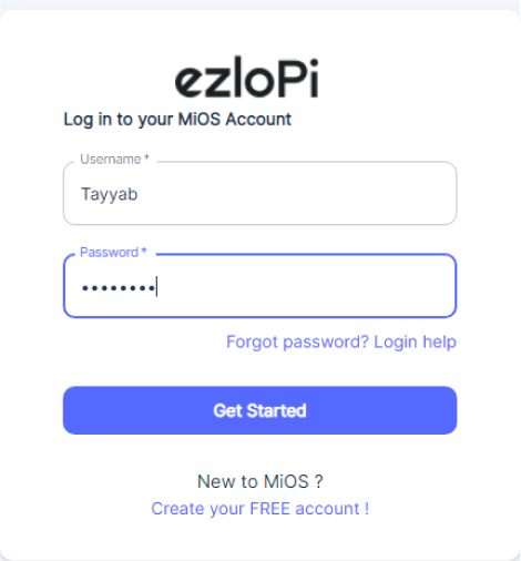
- Log in using the credentials which you just set earlier while signing up.

- Now, click on the Connect Device button and a pop-up window will appear.

Now, select COM Port to which your ESP32 device is connected. In our case, the COM3 port is used.
Click Connect.

- If you are new to this and it’s your first time configuring, select Create new Device ID. Enter Wifi SSID and Wifi Password.
- In the Device Configuration, tab click on I2C.

- A Digital Input window will open for inputting the following parameters:
- Set a device name of your choosing. In our case, we set it to BMP280.
- Set Device Sub Type to BMP280 I2C.
- Set the Slave Address to 118.
- Set the SDA pin to 21.
- Set the SCL pin to 22.
- Tick the “Enable Pullup” for both the SDA and SCL.
- Now Click the Apply button. After clicking the apply button you can see a table of your setting in the device configuration tab.
- Press the Flash Device button.

- A window will appear on the bottom left side of the screen displaying “Please press BOOT button while flashing begins.”
- Hold the BOOT button down until the next window appears on the bottom right side of the screen which says “Installation prepared. Please release the boot button now.”

- Release the BOOT button from your ESP32 when this pop-up on the bottom right window appears.

- After some time, a popup will appear saying Device Flashed Successfully! This means that your device has been set up successfully.
4. MiOS App
You can download the MIOS Android app from the Google Play Store and Apple App Store.


- After downloading the app, proceed to install the application and open it.
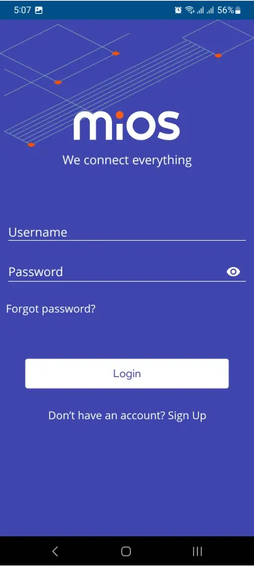
- Using the MIOS mobile application, create a new Ezlo Cloud account using the sign-up option. If you already have an account, you may proceed to log in.
- After successfully logging in, you will be able to see the number of controllers connected such as a lamp, fan, or any other device in the MiOS app. Tap on any controller of your desired ID:

- You will be able to see the status of your controller whether it is online or offline. Access the device dashboard, and tap the device. The following view of the dashboard will appear:

- After opening the dashboard, you will be able to see the tile of your connected device.
- As we can see above in the MiOS mobile app dashboard, the BMP280 sensor module tile is showing the current temperature and pressure values.
5. MiOS Web Application
- After configuring the controller with the EzloPi web flasher, head to ezlogic.mios.com
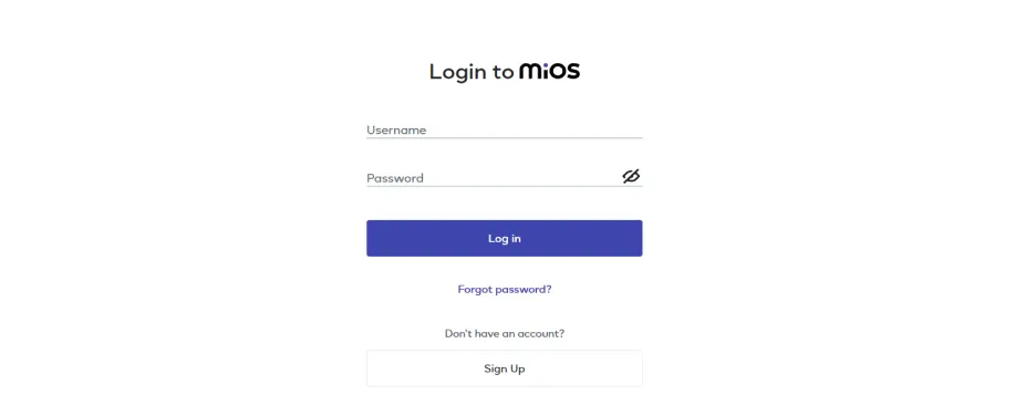
- Use the same credentials to log in that you used for configuring the controller with the web flasher.

- As seen in the web dashboard, the BMP280 module connected to the EzloPi device is displaying the ambient temperature and current pressure readings.


