Infuse Your Space with Intelligent Responsiveness with EzloPi!


GY-61 3-Axis Accelerometer
The EzloPi smart devices provide automation through simple, customizable use with our open-source EzloPi platform, making daily life easier and improving human-machine interactions.
Before moving into this example, it is very important to know about the device registration, provisioning and converting the ESP32 device into an EzloPi device along with knowledge of Web Flasher, MiOS Mobile Application for Android/iOS and the MiOS Web Application.
1. About this example
This project aims to seamlessly integrate the GY-61 3-axis accelerometer module with the ESP32-based EzloPi smart device, unlocking a realm of dynamic possibilities for smart environment interaction. By connecting the GY-61 accelerometer to the EzloPi device, users can harness real-time acceleration data to enrich home automation, IoT applications, and personalized experiences.
GY-61 accelerometer when combined with the versatile EzloPi platform, can be used to design creative automation scenarios where specific movements trigger predefined actions, enhancing the smart home experience.
2. Circuit Setup & Interfacing
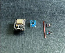
The following components are required for interfacing the touch sensor using the EzloPi device:
- ESP32 as EzloPi smart device.
- TT223B Capacitive Touch Sensor Module
The wiring diagram is represented as follows:
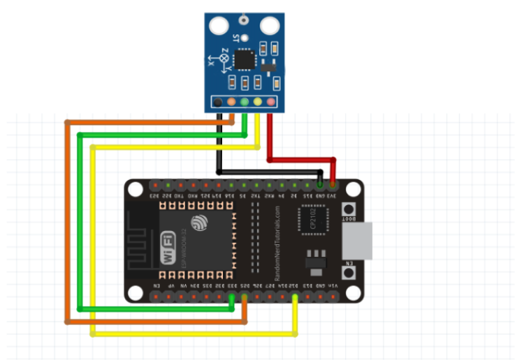
The following connections are made to complete the circuit setup.
From ESP32 (30 pins) to the GY-61 module:
- Connect the GND from the ESP32 to the GND pin of the GY-61 module.
- Connect the D32 pin from the ESP32 to the GY-61 pin labeled with X_OUT.
- Connect the D33 pin from the ESP32 to the GY-61 pin labeled with Y_OUT.
- Connect the D25 pin from the ESP32 to the GY-61 pin labeled with Z_OUT.
- Connect the Vin pin from the ESP32 to the GY-61 Vcc pin.
The wiring diagram of ESP32 38 pin is also represented as below:
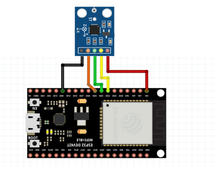
The following connections are made to complete the circuit setup.
From ESP32 (38 pins) to the GY-61 module:
- Connect the GND from the ESP32 to the GND pin of the GY-61 module.
- Connect the IO32 pin from the ESP32 to the GY-61 pin labeled with X_OUT.
- Connect the IO33 pin from the ESP32 to the GY-61 pin labeled with Y_OUT.
- Connect the IO25 pin from the ESP32 to the GY-61 pin labeled with Z_OUT.
- Connect the Vin pin from the ESP32 to the GY-61 Vcc pin.
3. Interfacing the GY-61 Accelerometer module using EzloPi Web Flasher
1. Set up your device/hardware by visiting config.ezlopi.com
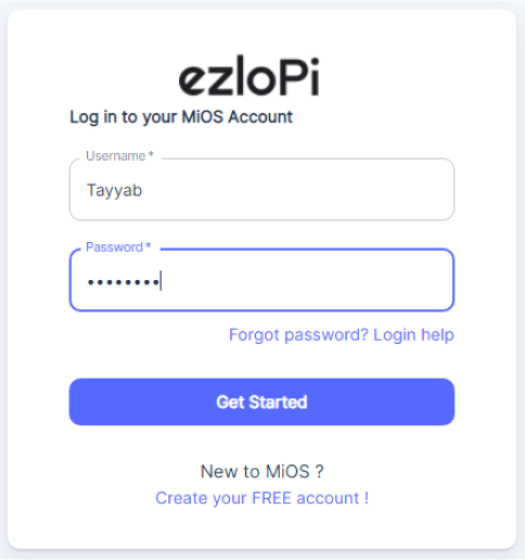
- Log in using the credentials that you just set earlier while signing up.
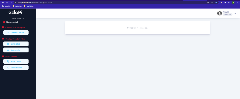
- Now click on Connect Device and a pop-up window will appear

Now, select the COM Port to which your ESP32 device is connected. In our case, the COM3 port is used.
Click Connect.
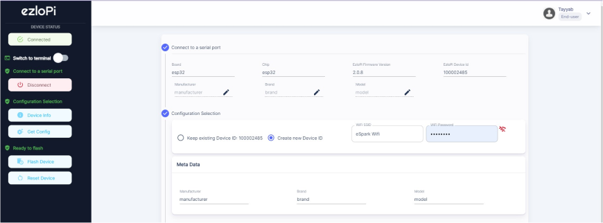
- If you are new to this and it’s your first time configuring, select Create new Device ID. Enter Wifi SSID and Wifi Password.
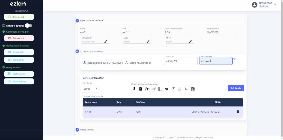
- In the Device Configuration, tab click on Analog Input.
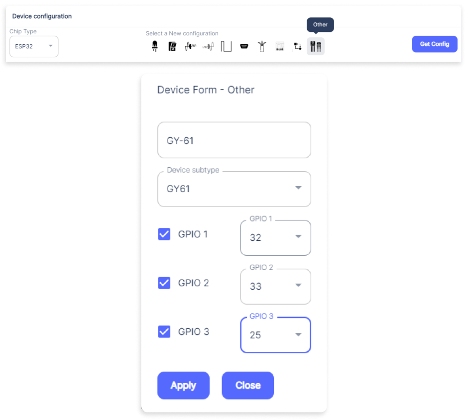
- A window will open for inputting the following parameters:
- Set a device name of your choosing. In our case, we set it to GY-61.
- Set Device Subtype to GY61.
- Check the checkbox of GPIO 1, GPIO 2, and GPIO 3.
- Set the GPIO 1 to 32, GPIO 2 to 33, and GPIO 3 to 25.
- Now Click the Apply button.
- After clicking the apply button you can see a table of your settings in the device configuration tab configuration tab.
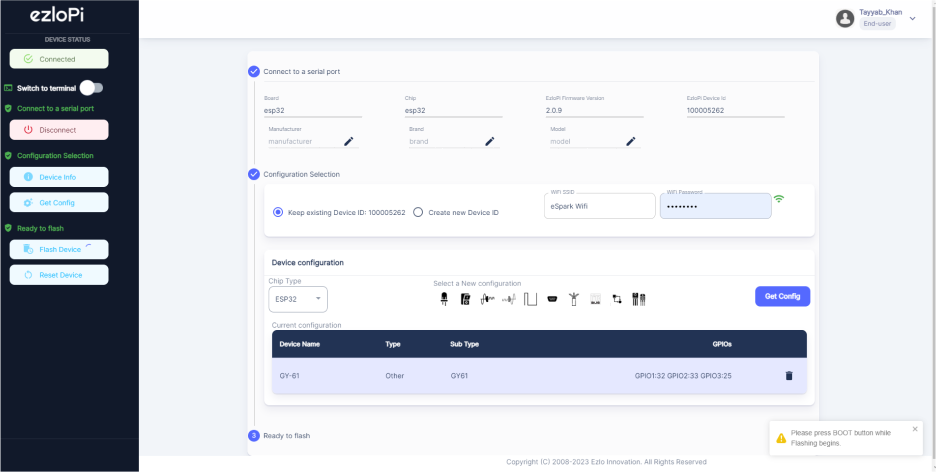
- Press the Flash Device button.
- A window will appear on the bottom left side of the screen displaying “Please press BOOT button while flashing begins.”
- Hold the BOOT button down until the next window appears on the bottom left side of the screen which says “Installation prepared. Please release the boot button now.”
- Release the BOOT button from your ESP32 when this pop-up on the bottom right window appears.
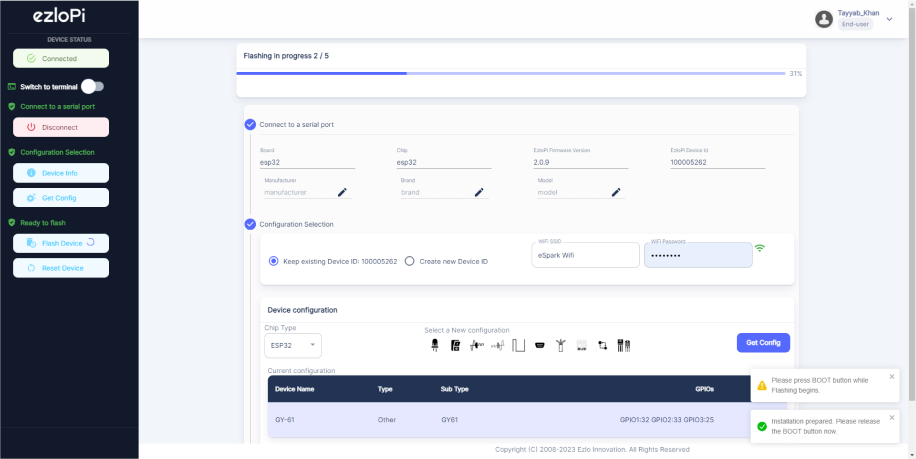
- After some time, a popup will appear saying Device Flashed Successfully! This means that your device has been set up successfully.
4. MiOS App
You can download the MIOS Android app from the Google Play Store and Apple App Store.


- After downloading the app, proceed to install the application and open it.
- Using the MIOS mobile application, create a new Ezlo Cloud account using the sign-up option. If you already have an account, you may proceed to log in.
- After successfully logging in, you will be able to see the number of controllers connected such as a lamp, fan, or any other device in the MiOS app. Tap on any controller of your desired ID:
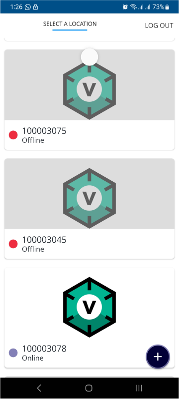
- You will be able to see the status of your controller whether it is online or offline. Access the device dashboard, and tap the device. The following view of the dashboard will appear:
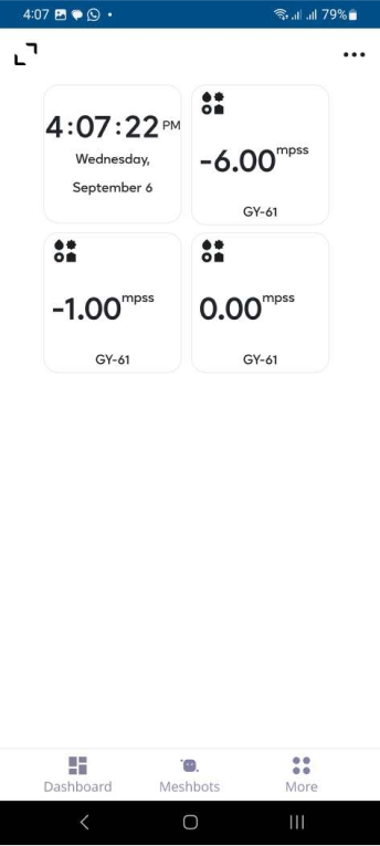
- Now, you will see three tiles on the MiOS mobile dashboard, each of them representing the acceleration values along the X, Y, and Z axis.
- Accelerometers are useful for sensing vibrations in systems or for orientation applications. So, when the GY-61 module changes its orientation on any axis, the above values will also vary.
5. MiOS Web Application
- After configuring the controller with the EzloPi web flasher, head to ezlogic.mios.com
- Use the same credentials to log in that you used for configuring the controller with the web flasher.
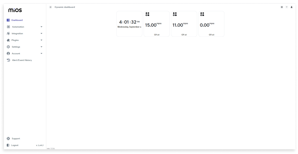
- As we can see on the MiOS web dashboard, the three tiles each represent the acceleration values along the X, Y, and Z axis as displayed above. When the GY-61 module changes its orientation on any axis, the above values will vary.

eZlopie Products A single-channel 5V relay module $00.00

eZlopie Products Momentary switch $00.00

eZlopie Products Level Shifter Module (BSS138) $00.00

eZlopie Products ESP32
$00.00

eZlopie Products AC Lamp and Holder
$00.00

